Lab 7 - EE420L 

Authored by Rodolfo Gutierrez

gutie284@unlv.nevada.edu

4/4/2016

Design of an audio amplifier


For the push pull topology we know that

    Vout/Vin = Rf*(gmp + gmn)  

With the datasheet we know that gmp + gmn = 10.7m + 18.3m = 19m

Meaning that our gain will be Vout/Vin = 19m * Rf

This is assuming that the transistors are operating in the saturation region. With VDD = 10 V, we can assume that the gate voltage will be large.

Schematic.PNG

   Since the given schematic was for comparing audio operations with and without a gain circuit we can ignore the 8 Ohms resistor connected directly to Vin. To ensure that Vin enters the circuit, Rin has been reduced slightly, and we have increased our VDD to 10 Ohms

    Simulations.PNG
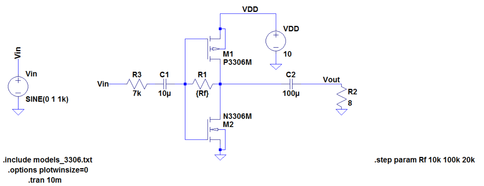
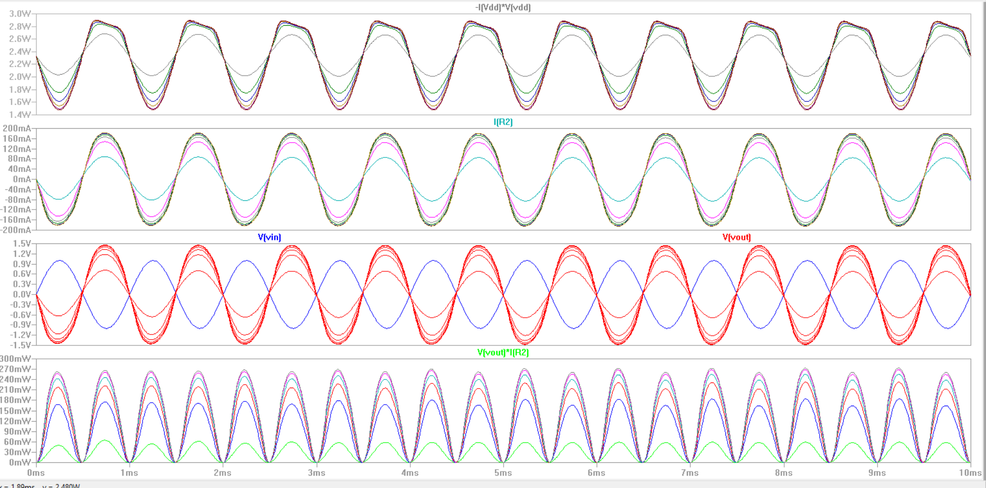
    Next we sweep Rf to see the effects of our gain with an 8 Ohm load. Here we find that the power is averages to about 2.2 W, which is not too high. We get a gain for values of Rf>20k. This gain saturates to about 1.5V. We also find that the power through our transistor is about 270 mW.
    power.PNG
    We know from our datasheet that we can have a power dissupation of about 625 mW. Since 270 mW falls under this value we don't need to compinsate for it.

    Rin = 6.7k Ohms
    Rout = 7.6 Ohms
    Rf = 100k 
    Our output swing was about 250 mV


    measured..jpg

    Here we see that at an imput of 200 mV we have an output gain of 250 mV. We also see from the scope measurement that we have a lot of noise, since this is also an amplifer this noise gets amplified. 


Return