Lab 5 - EE420L
Authored
by Rodolfo Gutierrez
gutie284@unlv.nevada.edu
3/4/2016
Op-amps
III, the op-amp integrator
- Calculate the frequency response of the following
circuit. Ensure you show your clear hand calculations.
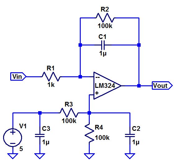
(Vin - 0)/R1 = (0 - Vout)/C1
C1/R1 = -Vout/Vin
C1 = 1/jwC
Vout/Vin = -1 *(-j)/wRC
Vout/Vin = j/wRC = 1/ 2*pi*1k*1u = 159.15 Hz
With the +j we can state that the gain leads by 90 degrees
- What can you neglect to simplify the calculation?
Since frequency response requires AC signals we can ignore the 2.5 V
entering Vp. The 100k resistor can also be ignored due to it being
large enough to block AC current flow.
- Does the circuit work if you remove the 100k? Why
or why not?
In
an ideal scenario the circuit would work, however in the real world you
would have a DC offset, so the 100k resistor is there to compensate the
offset.
- Does the 100k have much of an effect on the
frequency response?
No
because the resistance is too large for AC current to flow through. In
comparison the 1u capacitor is closer to a short circuit.
- Verify your calculations with experimental results.
- Show, at the unity-gain frequency of the
integrator, that the input and the output have the same peak values.
- Is the phase shift between the input and the output
what you expect? Why or why not?
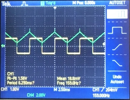
We see that we get a triangular output for our square input at 159 Hz,
confirming our calculations for unity gain frequency.We see that the
output is leading the input by 90 degrees, which we should expect from
the +j term in the frequency response.
- Next, design, simulate, and build a square-wave to triangle
wave generation circuit.
- Assume the input/output frequency is 10 kHz and the output
ramp must swing from 1 to 4 V centered around 2.5 V.
- Show all calculations and discuss the trade-offs (capacitor
and resistor values, input peak, min, and average, etc.)
Vout = T*Vin / 2RC
4 -1 = 2.5*(1/10k) /2RC
RC = 2.5/10k /6 = 41.667 u
Next
we can decide either the resistor value or capacitor values. Since it
would be easier to acquire unique sized resistors, it would be simpiler
to choose the capacitor size
R = 41.667 u / C
We see that
if C = 1u, then we will have to use a 41.667 sized resistor. We would
rather use a smaller capacitor to get a larger resistor. At C = 0.01u
R = 4166.7 Ohms
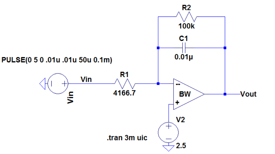
Next
we simulate the circuit with our calculated values for R and C, this is
to insure that we will get a triangular output that falls within the
given constraints.
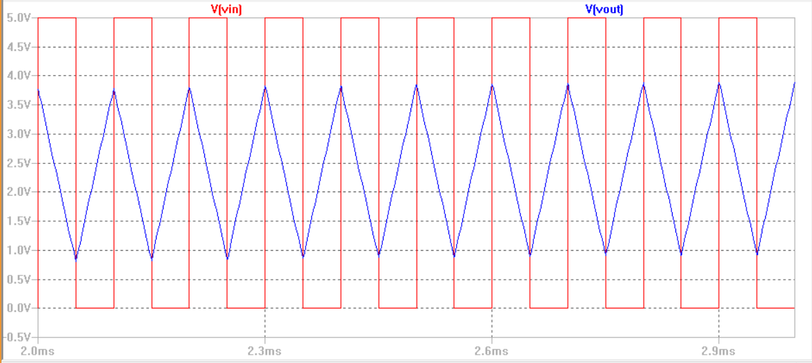
Here we see that our Vout meets the given requirements.
In the lab experiment we see a output waveform that nearly matches our experimental results
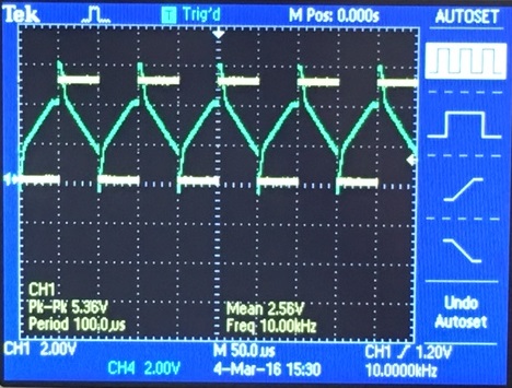
Here at 10kHz we get a triangle output, centered at 2.5 volts. Now the
reason why the tips of the triangle wave spike up is because we are
using a small capacitor, if the capacitor was larger we would have
smoother triangle edges, as seen with the intergrator output seen in
the first experiment. Sofor the trade-off between the resistor and
capacitor is that if the capacitor is too small we will have larger
edge spikes in our
intergrator. However if the capacitor is too big we would need to use
small resistors to compensate the RC size. We would try improving the
design by using a 1k resistor with a 41.667 nF capacitor, although
obtaining that capacitor in the lab would require combining smaller
capacitors together, we should see an improvment in our output signal.
Return