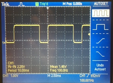
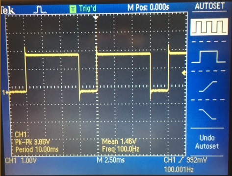
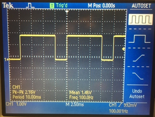
- Show scope waveforms of a 10:1 probe undercompensated, overcompensated, and compensated correctly.
under compensation over compensation perfect compensation
- Comment on where the type of scope probe (i.e., 1:1, 10:1, 100:1, etc.) is set on your scope (some scopes detect the type of probe used automatically).
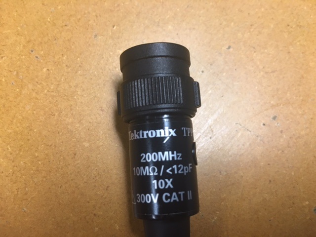
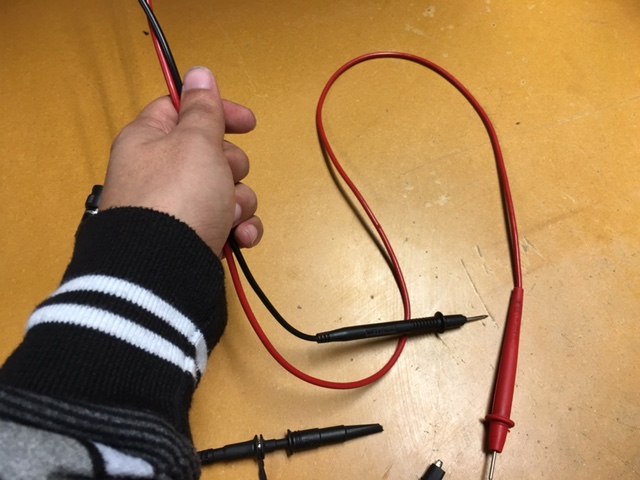
Details about the cable can be found near the input of the cable, as shown in the
image above. The 10X indicates that it is a 10:1 probe
- Draft the schematic of a 10:1 scope probe showing: the 9 MEG resistor, 1 MEG scope input resistance, capacitance of the cable, scope input capacitance, and capacitance in the probe tip.
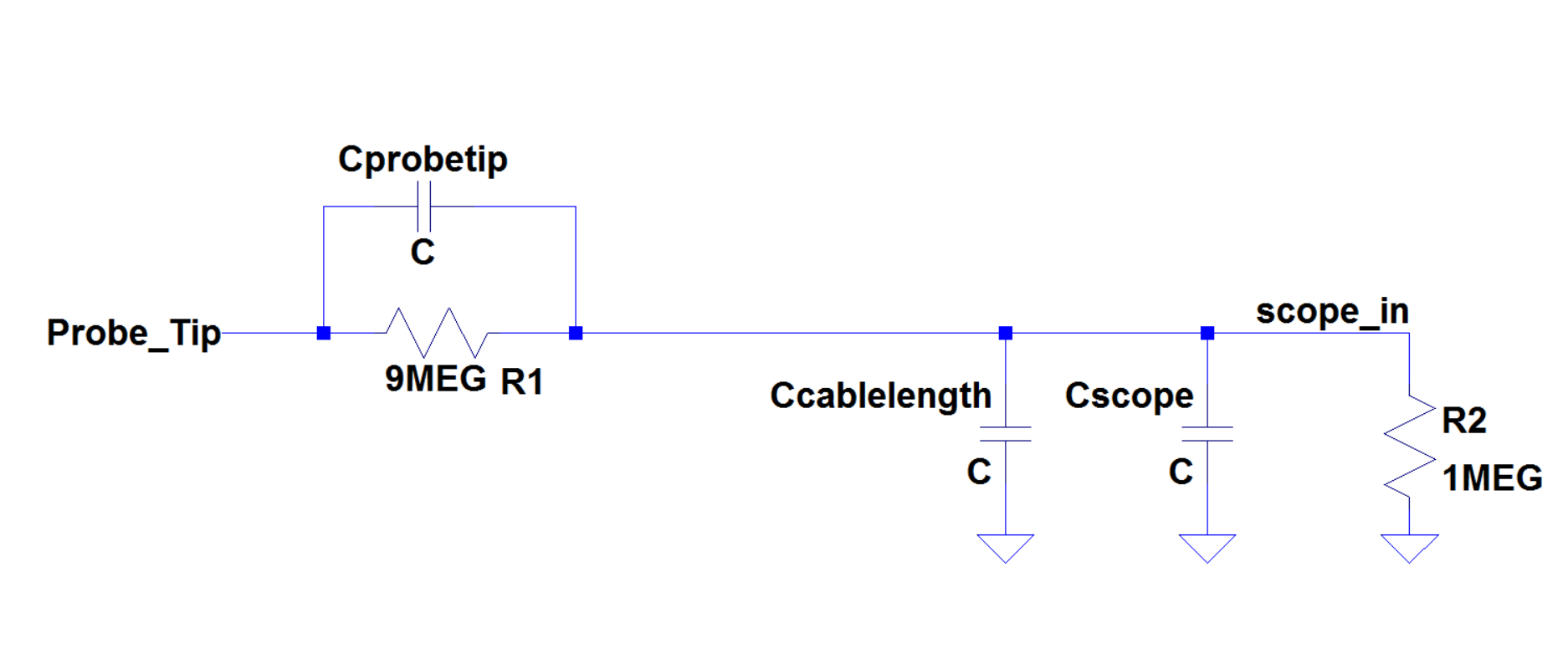
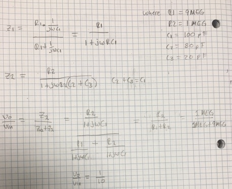
- Using circuit analysis, and reasonable/correct values for the capacitances, show using circuit analysis and alegbra (no approximations), that the voltage on the input of the scope is 0.1 the voltage on the probe tip.
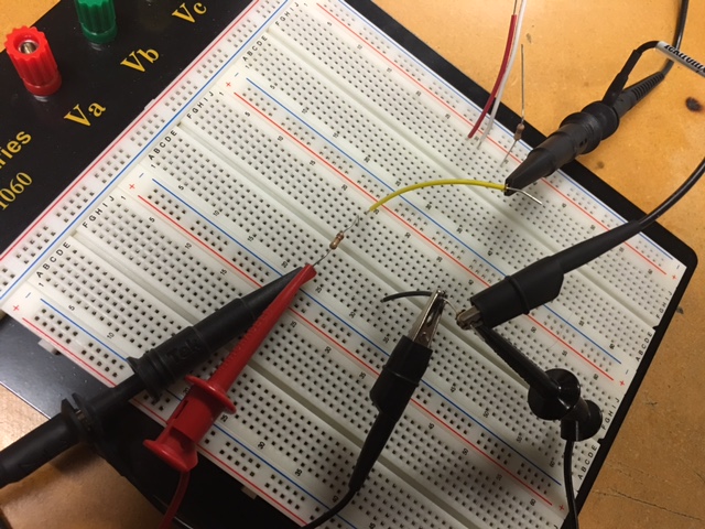
- Devise an experiment, using a scope, pulse generator, and a resistor, to measure the capacitance of a length of cable. Compare your measurement results to the value you obtain with a capacitance meter. Make sure you show your hand calculations.
By connecting the resistor and scope probe in series we create a RC circuit with the probe as our capacitor.
The next step is to measure the time delay of our capacitor. By using
the formula Td = RC we are able to determine the capacitance with our
known resistor (100k) and the measured time delay. We can rewrite this
formula as
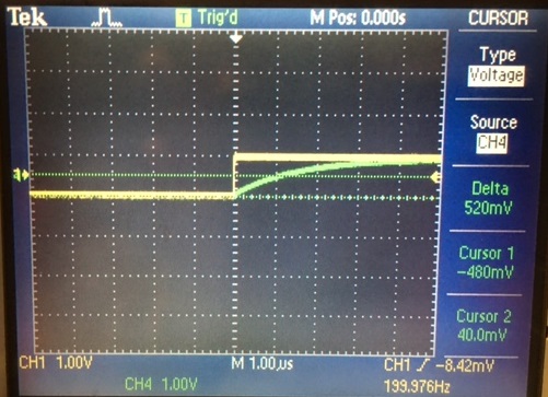
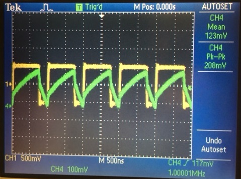
The images blow shows both the amplitude and time of our output voltage. We know that for half of Vin's amplitude the time delay is equal to 0.7RC so then we repeat the measurements for when T = 1 and when T = 5 which will have Vin's amplitudes of 0.63V and 1 V respectively
C = Td/ (X*R)
Where X is the amount of T at a particular amplitude for Vout. For
example T is equal to 1 when Vout charges at 0.63 * Vin. Vin was set at
1V to simplify calculations.
The images blow shows both the amplitude and time of our output voltage. We know that for half of Vin's amplitude the time delay is equal to 0.7RC so then we repeat the measurements for when T = 1 and when T = 5 which will have Vin's amplitudes of 0.63V and 1 V respectively
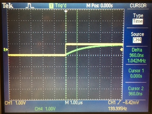
| Vout | T | Time Delay | C |
| 0.5V | 0.7 | 960ns | 13.7 pF |
| 0.63V | 1 | 1.120us | 11.2 pF |
| 1V | 5 | 5.2 us | 10.4 pF |
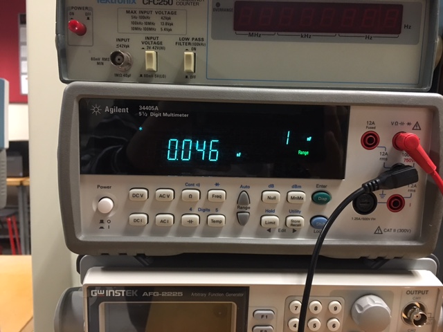
To confirm our estimated capacitances a multimeter was used. However the
readings claimed that the capacitace was about 46 pF.
This was due to the extra capacitance of the wire probes used to measure our cable. The images below shows that there is a capacitance of 35 pF when our cable is not connected to the multimeter
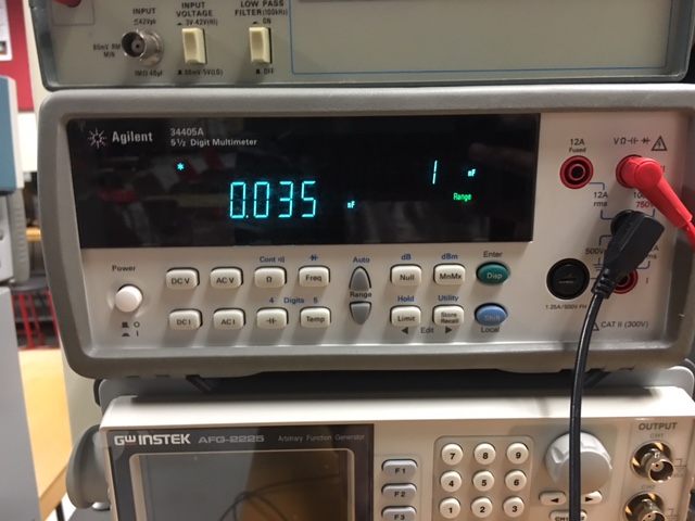
So we can conclude that the multimeter is adding in capacitance to its
measurements of our cable. Meaning that the cables capacitance is lower
than 46 pF.
- Build a voltage divider using two 100k resistors. Apply a 0 to 1 V pulse at 1 MHz to the divider's input. Measure, and show in your report, the output of the divider when probing with a cable (having a length greater than or equal to 3 ft) and then a compensated scope probe. Discuss and explain the differences.
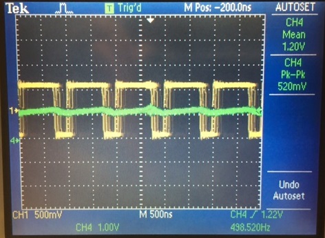
When we connect a cable without the compensation probe we notice that
at high frequencies the output voltage nearly becomes zero. Meaning
that the capacitance inside of the cable is preventing the scope from
reciving the input voltage. Which is expected because capacitors act
like an open at high frequencies.
With
the compensated scope probe we are able to see the output voltage. This
is due to the decreased capacitance that the compensated probe provides
over a non-compensated cable.
- Finally, briefly discuss how you would implement a test point on a printed circuit board so that a known length of cable could be connected directly to the board and not load the circuitry on the board.
We should add a resistor and capacitor in parallel at the test point to
ensure that cables capacitance doesn't effect the PCB circuit as seen
with the uncompensated cable experiment.