Lab 7 - EE 420L
Author: Dane Gentry
Email: gentryd2@unlv.nevada.edu
April 6, 2016
Design of an Audio Amplifier
Click on any picture for its full size!
Pre-lab work
- This lab will again utilize the ZVN3306A and ZVP3306A MOSFETs., so review lab 6.
- Review these datasheets and become familiar with these transistors.
Lab Description
- Learn
and experience how to design, build, and test an audio amplifier.
Lab Requirements
Design
an audio amplifier (frequency range from roughly 100 Hz to 20 kHz)
assuming that you can use as many resistors, ZVN3306A transistors, and
ZVP3306A transistors as you need along with only one 10 uF capacitor
and one 100 uF capacitor. Assume that the supply voltage is 10 V, the
input is an audio signal from an MP3 player (and so your amplifier
should have at least a few kiloohms input resistance), and the output
of your design is connected to an 8-ohm speaker (so, ideally, the
output resistance of your amplifier is less than 1 ohm).
- Your lab report should detail your thoughts on the design of the amplifier including hand-calculations.
- A good place to start is with the push-pull amplifier characterized in lab 6.
- Simulate your design. Document the results in your lab report.
- Build and test your design.
- Document the performance of the design including power dissipation, output swing, input resistance, output resistance.
For the following questions and experiments assume VCC+ = +10 Volts
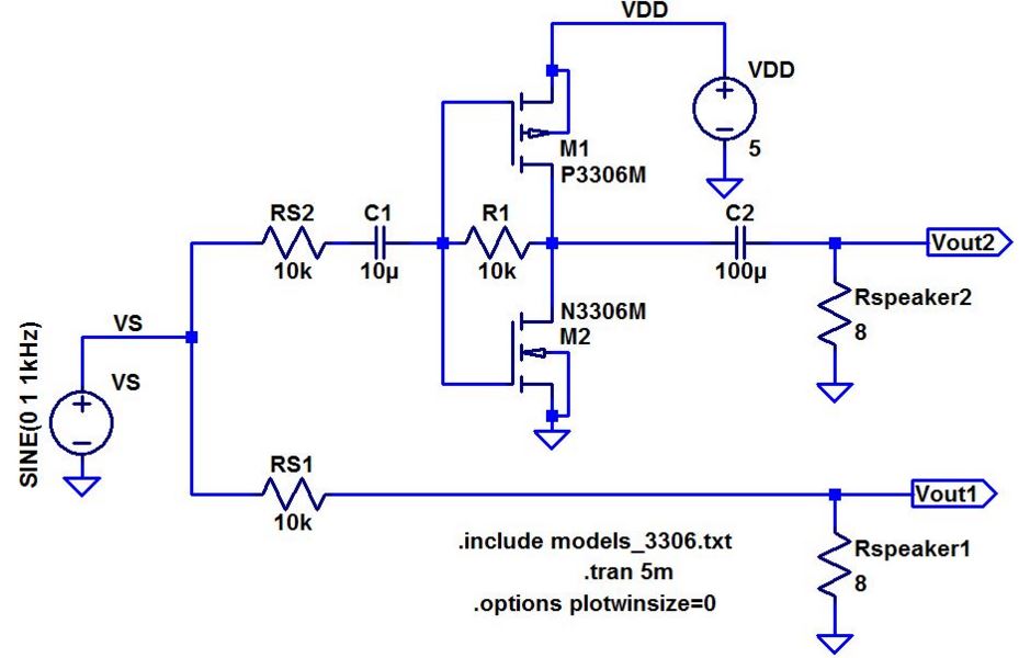
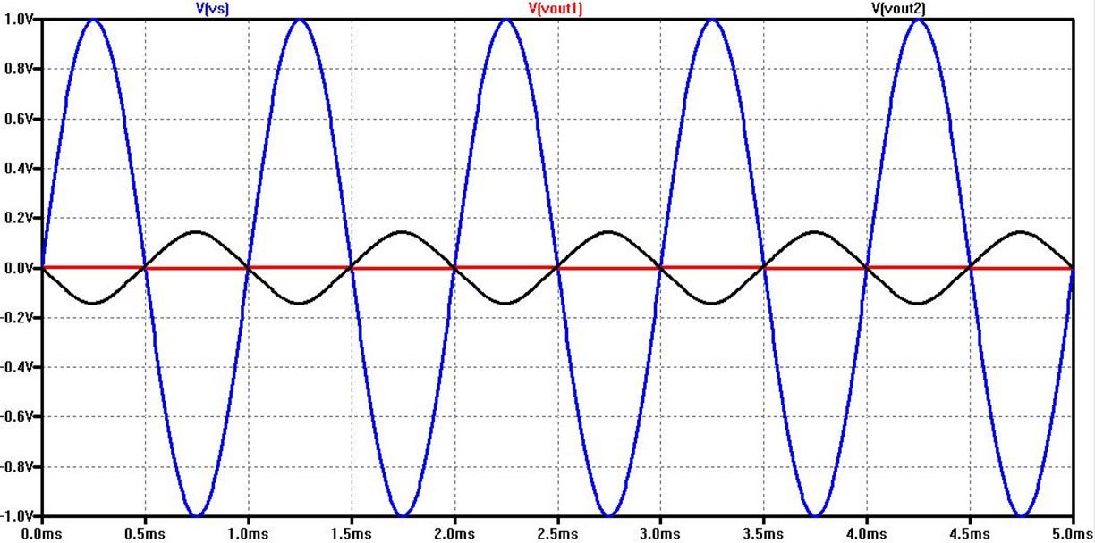
Below
is a comparison between driving a speaker without (red, Vout1) and with
(black, Vout2) an audio amplifier. The source resistance is 10k meaning
that the source can supply 1 V (blue, Vs) at 100 uA maximum. The
simulation files used to generate this figure are found in lab7_sims.zip.
Schematic
Waveform Simulation
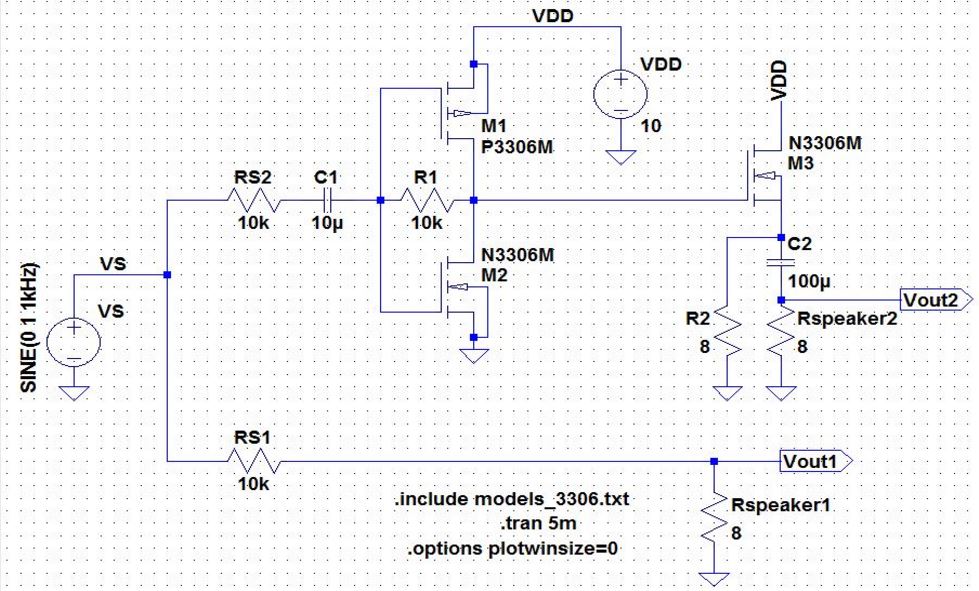
Improved Audio Amplifier Design
Our
audio amplier design utilizes the push pulll amplifier from Lab 6. This
topology incorporates the same principle as a voltage divider such that
the output voltage is large when the output resistance (resistor from
output to ground) is large while the input resistance (resistor from
input to output) should be small, and vice versa. The output resitor in
our audio amplifier is the 8 ohm speaker load that the amplifier will
be driving. The input signal will be amplified at the output to produce
louder audio out of the speaker. Our audio amplifier has a calculated
gain of Vout/Vin = Rf*(gmp+gmn) without the speaker load. In order
to better match the speaker load, a smaller output resistance was
provided to our amplifier by adding a second stage source follower
which decreases the output impedance while the gain is close to 1.
Schematic
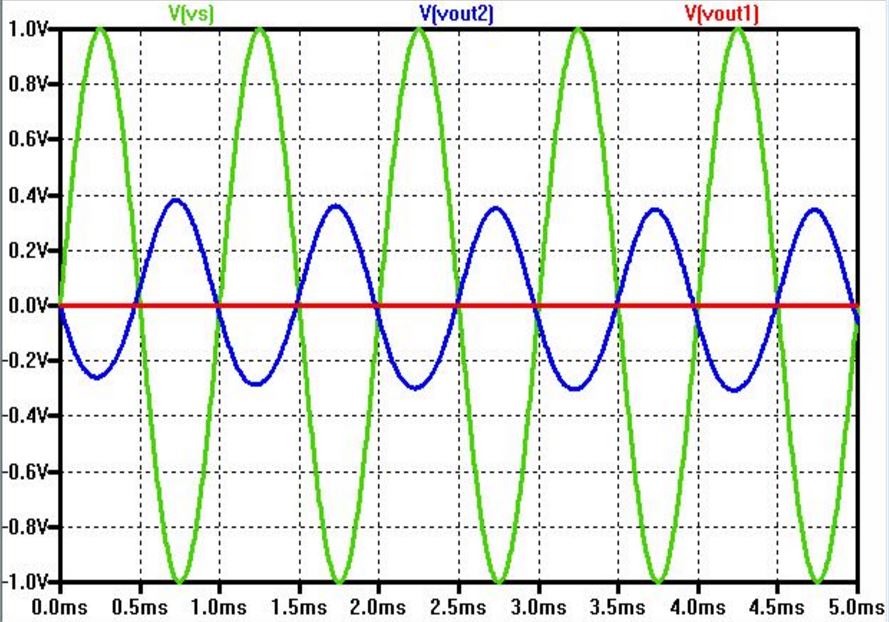
Waveform Simulation
Input
Resistance
Output Resistance
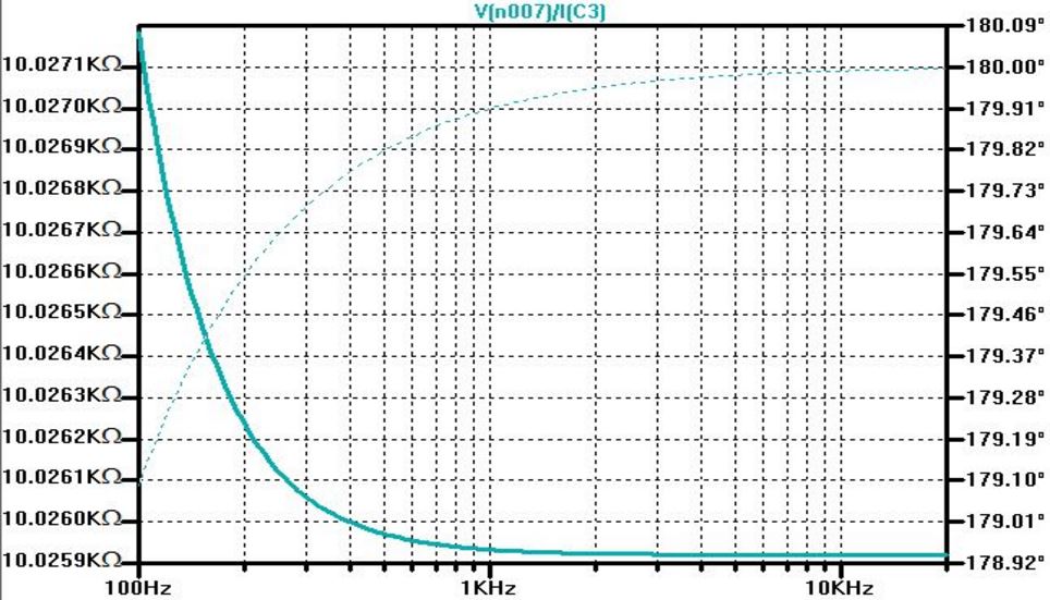
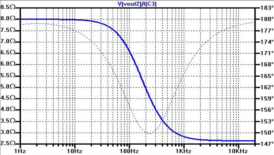
The
output resistance is simulated to be roughly 10k ohms while the input
resistance is simlated to be 8 ohms, which makes sense because we are
using an 8 ohm speaker load for the amplifier to drive.
Power Consumption Simulation Power Consumption - Voltage/Current Measurement
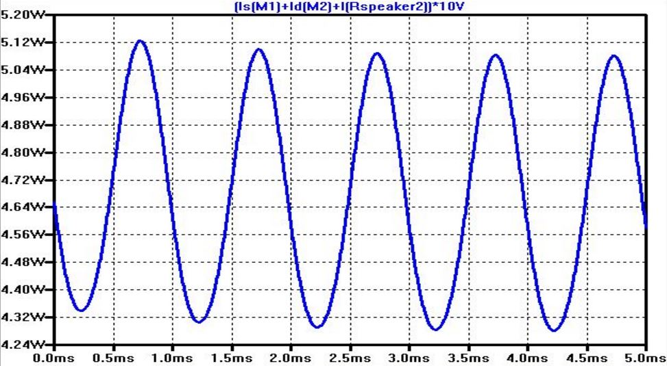

Power Consumption Calculation:
The
power consumption of the improved design of the audio amplifier circuit
was simulated in LTSpice to provide a power consumption that swings
between 4.3W (Watts) and 5.12W. The power consumption was then
calculated by measuring the voltage (VDD) and drain current of the
circuit. The voltage was measured to be 10V while the current was
measured to be 282mA. This gives a power consumption of 2.8W b/c 10*280mA = 2.8W.
Experimental Results
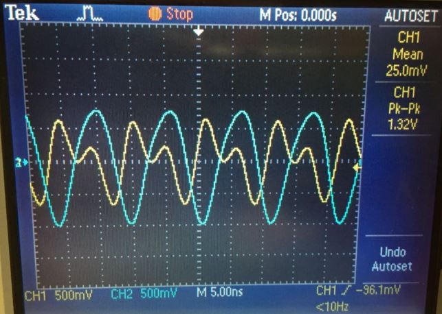
Simulations, and experimental results all agree.
Lab Conclusion
This
lab demonstrated the design, building, and testing of an audio amplifier utilizing the push-pull amplifier topology. The
output of our 2 stage amplifier is an improvement upon the 1 stage
amplifier, but the audio signal was both amplified and reduced due
to mismatching of impedances since the output of a source follower is
significantly smaller than that of the push pull amplifier while our
speaker load (8 ohms) is very small, so the output resistance is not small enough to drive the speaker. Ideallly, the output resistance would be smaller than
the 8 ohm speaker loud so that the output voltage would be greater. The
experiments in this lab provided excellent experience in how
to design, build, and utilize an audio amplifier, and all
experiments in this
lab were performed with little difficulty and few encountered problems.
Return to EE 420 Labs