Lab 6 - EE 420L
Author: Dane Gentry
Email: gentryd2@unlv.nevada.edu
March 30, 2016
Single-Stage Transition Amplifier
Click on any picture for its full size!
Pre-lab work
- This lab will utilize the ZVN3306A and ZVP3306A MOSFETs.
- Review these datasheets and become familiar with these transistors.
- Verify that the simulations seen in lab6_sims.zip reasonably model the behavior of the transistors' ID v. VGS, ID v. VDS, and gm v. VGS curves.
- Finally, watch the video single_stage_amps and review single_stage_amps.pdf
Lab Description
- Learn
and experience how to design, build, and test various amplifiers such
as common-drain, common-gate, common-source, and push-pull amplifiers.
Lab Requirements
Part 1:
Common-Drain Amplifier Schematic

Discuss the operation of these circuits.
For the source follower
aka common drain (CD) amplifier, the gate is tied to the the input
while the source is tied to the output, and the drain is common to
the input and output, hence common drain amplifier. The biasing of the amplifier is set by the voltage divider at the gate, and the source
resistor is used to determine VGS, the gate to source voltage, to
ensure the device operates in the saturation region. In addition, the
ACinput is shorted through a capacitor so that the biasing at the
gate is not affected. The source to bulk voltage, VSB, results in body
effect since the source and body are at different potentials (body tied
to ground) which results in an increase in VTH and consequent current
flow.
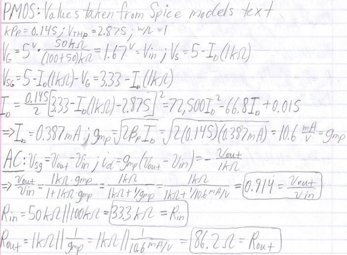
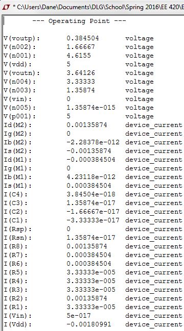
Hand Calculations

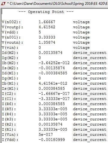
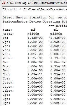
Simulations


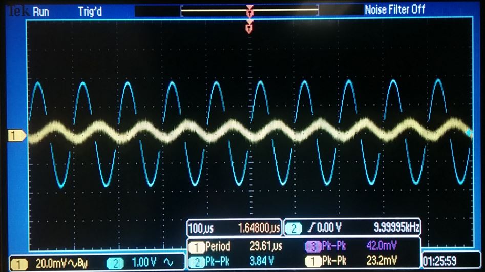
Experimental Results
| Gain | Input Resisstance | Output Resistance |
| NMOS |  |  | 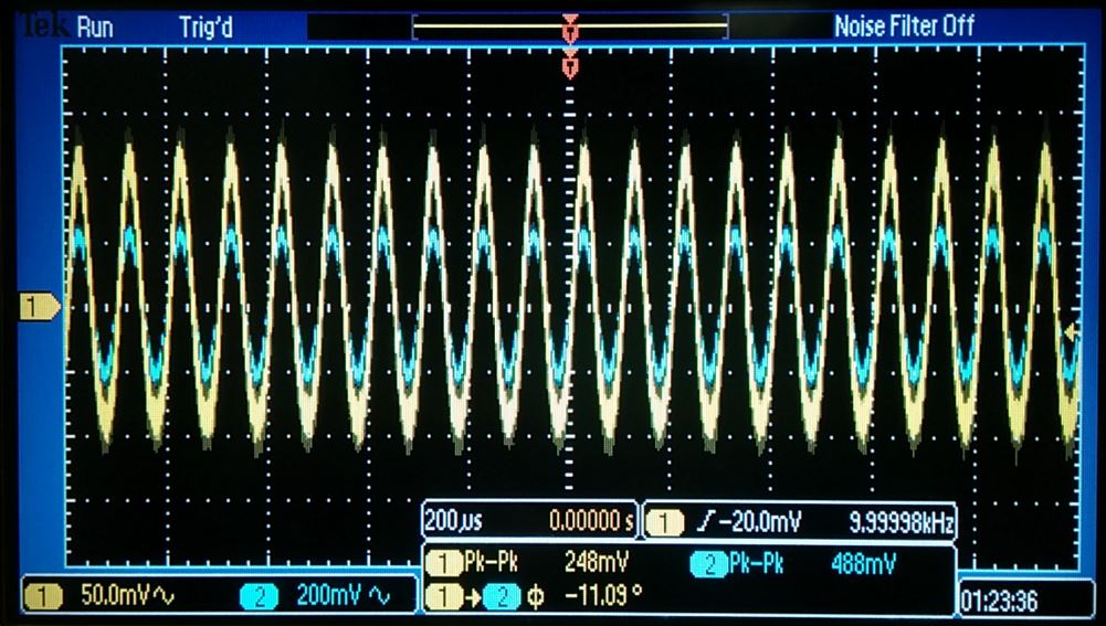 |
| PMOS |  | 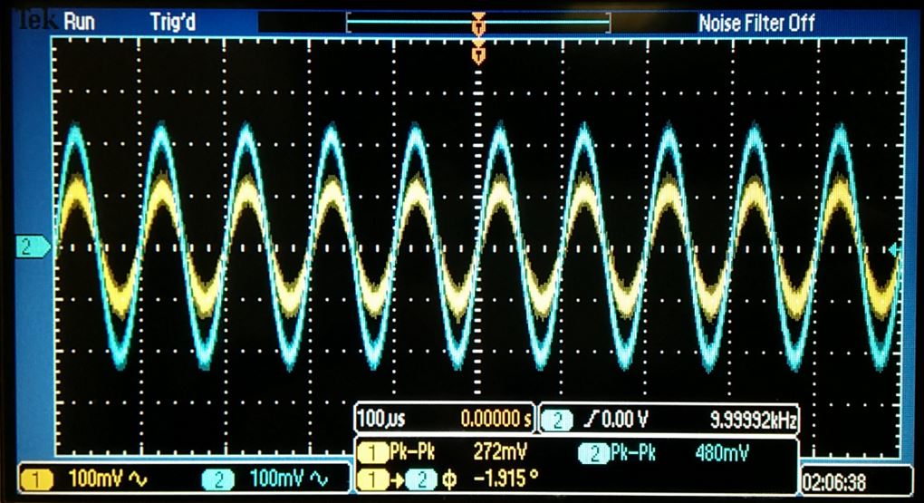 | 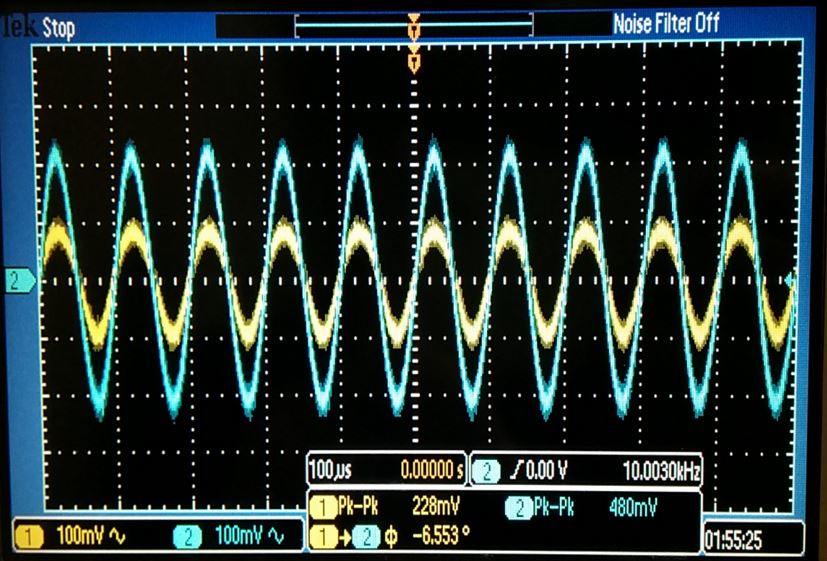 |
Theoretical hand calculations, simulations, and experimental results all agree.
Indicate why the "+" terminal of the capacitor shoulbe be connected to the gate of the MOSFET
- The
circuits in these laboratory experiments were all built using
electrolytic capacitors which are polarized between the anode and
cathode. The postitive terminal was connected to the gate of the MOSFET
because thepositive terminal of the capacitor should always be connected to the
more positive voltage in a circuit. Otherwise, the capacitor will
create a short between the terminals then overheat and explode.
Discuss how to measure the input resistance
- In
order to measure the input resistance of the previous circuit, a
resistor that is equivalent to the calculated value of the input
resistance is placed in series to the input resistance. The output
voltage of the created voltage divider will then be measured to be half
the input voltage.
Discuss how to measure the output resistance
- The
output resistance can be measured in a similar fashion as the input
resistance by placing creating a voltage divider and measuring the
output voltage to be half the input voltage since the resistors are
equivalent values.
Part 2:
Common-Source Amplifier Schematic
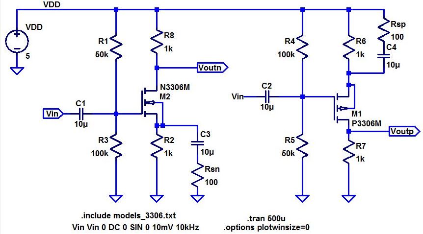
Discuss the operation of these amplifiers including both DC and AC operation.
The common-source(CS)
amplifier has the input at the gate and the output at the drain of the
device, thus the input and output have the source in common. The
voltage divider at the gate and the resistors in the drain and source
provide biasing and are set to keep the devices in the saturation
region. The capacitors are used for AC coupling, as in the
source-follower. Unlike the source-follower, the CS is utilized when a
larger gain is desired.
The two resistors,Rsn and Rsp, change the current and thus the voltage at the gate. These resistors are shown to be inversely proportional to gain.
Hand Calculations
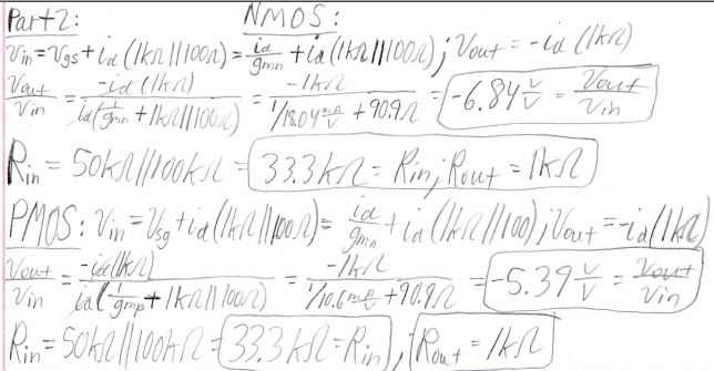
Simulations
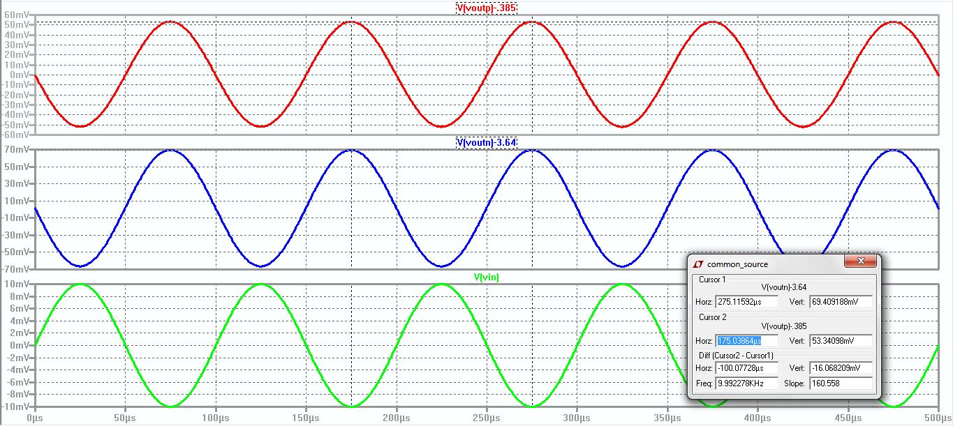

Experimental Results
| Gain | Input Resisstance | Output Resistance |
| NMOS | 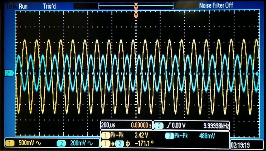 | 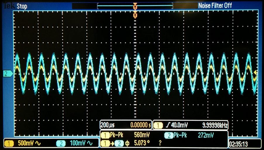 |  |
| PMOS | 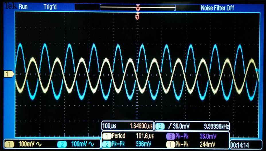 | 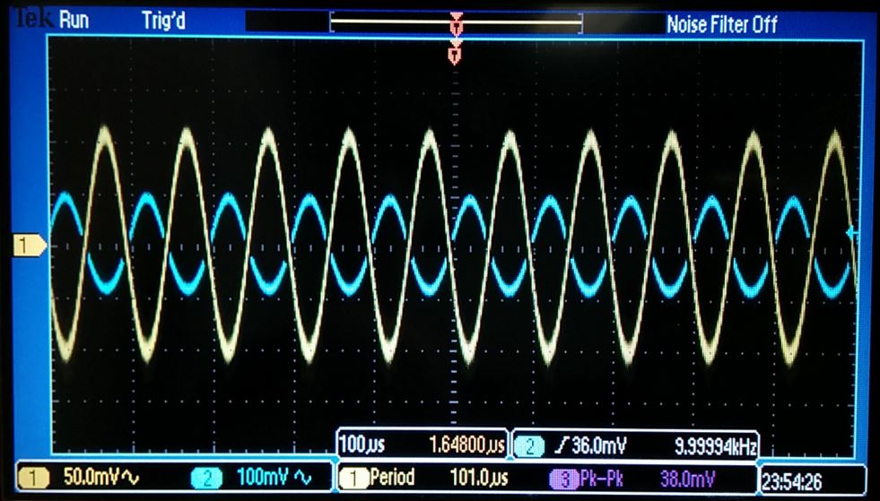 | 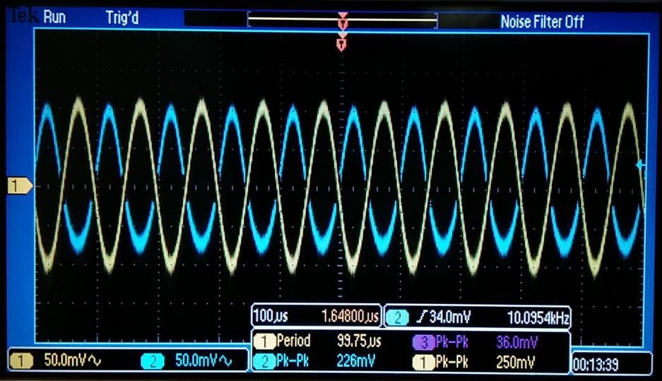 |
Theoretical hand calculations, simulations, and experimental results all agree.
Part 3:
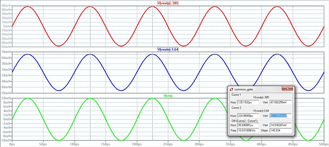
Common-Gate Amplifier Schematic
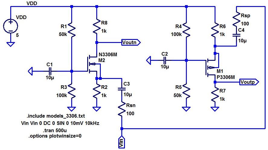
Discuss the operation of these amplifiers in your lab report including both DC and AC operation.
- For
the common gate (CG) amplifier, the input (connected to the
source) and the output (connected to the drain) are both connected
to a common gate. Common gate amplifiers have the same DC biasing as the common drain and common amplifiers but
have low input impedance and high output impedance resultin in high
voltage gain yet low current and power gain with the source resistances, Rsn and Rsp , inversely proportional to the gain.
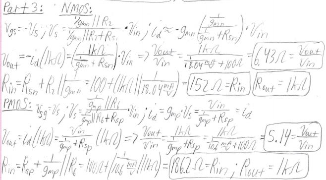
Hand Calculations
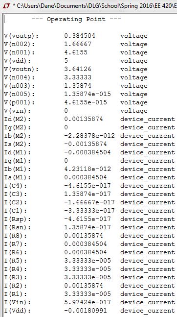
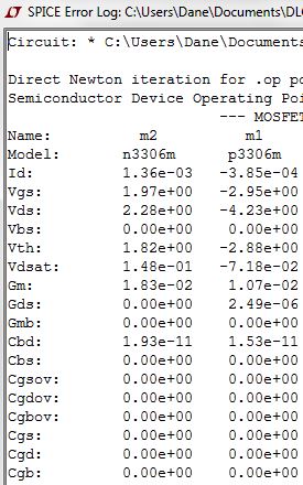
Simulations
Experimental Results
| Gain | Input Resisstance | Output Resistance |
| NMOS | 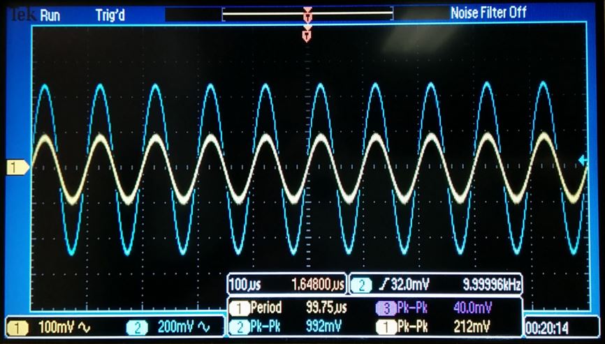 |  |  |
| PMOS | 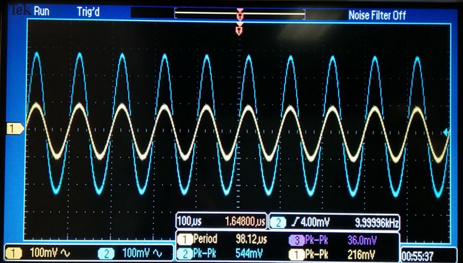 |  | 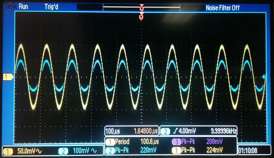 |
Theoretical hand calculations, simulations, and experimental results all agree.
Part 4:
Push-Pull Amplifier Schematic
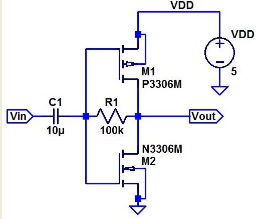
Discuss the operation of this amplifier including both DC and AC operation.
- The
output of a push-pull amplifier is designed to drive the current
through a load in two directions by using a PMOS and an NMOS to
source current through the load and sink current from the load.
Push-pull amplifiershave the practical function of sourcing/sinking current through the NMOS/PMOS with the output limited by the power rail. Push-pull amplifiers are used for low distortion, high efficiency and high output power.
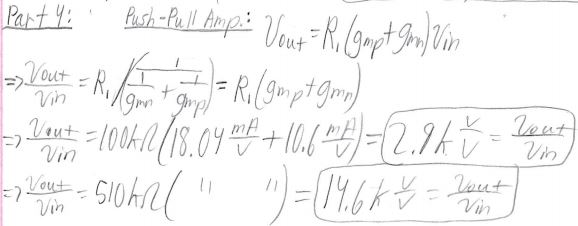
Hand Calculations
Simulations


Experimental Results
| Gain (100k Res) | Gain (510k Res) |
 |  |
Theoretical hand calculations, simulations, and experimental results all agree.
Lab Conclusion
This
lab demonstrated the operation and use ofcommon-drain, common-gate, common-source, and push-pull amplifiers. The
experiments in this lab provided excellent experience in how
to design, build, and utilize these amplifiers, and all
experiments in this
lab were performed with little difficulty and few encountered problems.
Return to EE 420 Labs