Lab 4 - EE 420L
Author: Dane Gentry
Email: gentryd2@unlv.nevada.edu
March 2, 2016
Op-Amps II, Gain-Bandwidth Product and Slewing
Click on any picture for its full size!
Pre-lab work
Lab Description
- Utilize the LM324 op-amp in order to learn and experiment with how Gain-Bandwidth Product and slewing affect non-ideal op amps.
For the following questions and experiments assume VCC+ = +5V and VCC- = 0V.
Part 1:
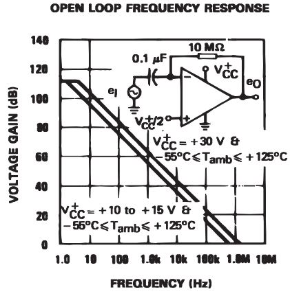
- Estimate, using the datasheet, the bandwidths for non-inverting op-amp topologies having gains of 1, 5, and 10.


- GBW of the LM324 op amp is 1.3MHz
- BW = GBW/|A| where |A| is the closed loop gain of 1, 5, and 10 such that |A| = |1 + (R2/R1)|
- For a gain of 1, the BW = GBW/1 = 1.3 MHz
- For a gain of 5, the BW = GBW/5 = 260 KHz
- For a gain of 10, the BW = GBW/10 = 130 KHz
Part 2:
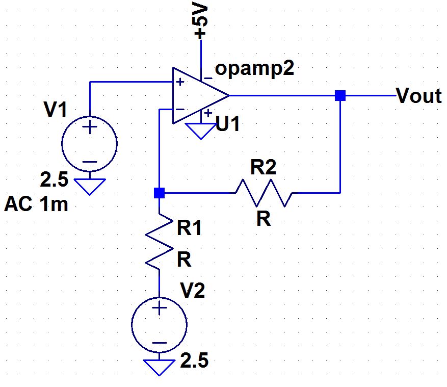
- Experimentally verify these estimates assuming a common-mode voltage of 2.5 V.
- Provide schematics of the topologies you are using for experimental verification along with scope pictures/results.
- Associated comments should include reasons for any differences between your estimates and experimental results.
| Non-Inverting Topology | Gain |
 | R1 is set to be 10k for all gains
For a gain of 1, R2 is set to be 0
For a gain of 5, R2 is set to be 40k
For a gain of 10, R2 is set to be 90k |
Experimental Results

3dB @ 1.77MHz | 
3dB @ 388 KHz |

3db @ 203.5KHz | At a gain of 1, 3dB = 1.77 MHz
At a gain of 5, 3dB = 388 KHz
At a gain of 10, 3dB = 203.5KHz |
Conclusion
The LM324 op-amp appears to have a much higher bandwidth than the theoretical values calculated using the datasheet. This is most likely due to variations in manufacturing of various LM324 op-amps. This higher bandwidth suggests the op-amp also has a much higher GBP than the theoretical values calculated using the datasheet.
Part 3:
- Estimate, using the datasheet, the bandwidths for inverting op-amp topologies having gains of -1, -5, and -10.
- GBW of the LM324 op amp is 1.3MHz
- IMPORTANT:
For inverting op-amp topologies, we must assume a non-inverting op-amp
topology with resistor values that correspond to the gain of
the inverting op-amp topology such that:
- BW = GBW/|A| where |A| = |1 + (R2/R1)| and (-R2/R1) is equal to the gain of the inverting op-amp.
- For
a gain of -1, (-R2/R1) = -1 OR (R2/R1) = 1 which gives |A| = |1 +
(R2/R1)| = |1 + 1| = |2| = 2 ==> |A| = 2
- BW = GBW/|A| = 1.3MHz/2 = 650 KHz
- For a gain of -5, (R2/R1) = 5 which gives |A| = 6
- BW = GBW/|A| = 1.3MHz/6 = 216.67 KHz
- For a gain of -10, (R2/R1) = 10 which gives |A| = 11
- BW = GBW/|A| = 1.3MHz/11 = 118.18 KHz
Part 4:
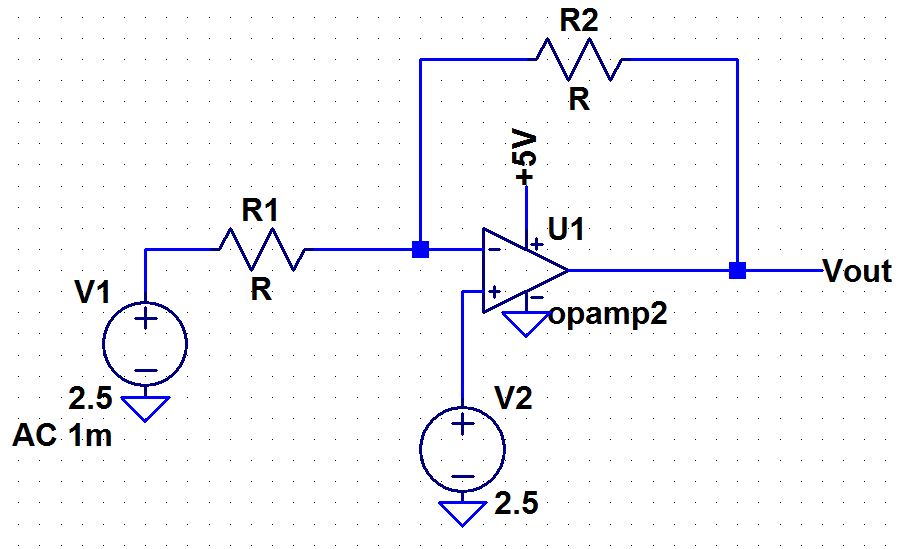
- Experimentally verify these estimates assuming a common-mode voltage of 2.5 V.
- Provide schematics of the topologies you are using for experimental verification along with scope pictures/results.
- Associated comments should include reasons for any differences between your estimates and experimental results.
| Inverting Topology | Gain |
 | R1 is set to be 10k for all gains
For a gain of -1, R2 is set to be 10k
For a gain of -5, R2 is set to be 50k
For a gain of -10, R2 is set to be 100k |
Experimental Results

3dB @ 1.26MHz | 
3dB @ 348 KHz |

3db @ 193KHz | At a gain of 1, 3dB = 1.265 MHz
At a gain of 5, 3dB = 348.5 KHz
At a gain of 10, 3dB = 193.5KHz |
Conclusion
The LM324 op-amp appears, again, to have a much higher bandwidth than the theoretical values calculated using the datasheet. This is most likely due to variations in manufacturing of various LM324 op-amps. This higher bandwidth suggests the op-amp also has a much higher GBP than the theoretical values calculated using the datasheet.
Part 5:
- Design
two circuits for measuring the slew-rate of the LM324. One circuit
should use a pulse input while the other should use a sinewave input.
- Provide comments to support your design decisions.
- Comment on any differences between your measurements and the datasheet’s specifications.
Experimental Results

Sinusoidal Slew Rate | 
Pulse Slew Rate |

Conclusion
This
experiment shows that for the slew rate of the sinusoidal input, the output must swing 2.56 volts (Pk-Pk) at a frequency of 202KHz. We can estimate the slew rate of the sinusoidal input then to be the input voltage of the sinusoid divided
by the period of the output (6.16/5) = 1.23 V/uS. This suggests the
experimental slew rate of the sinusoidal input is much smaller compared
to the theoretical slew rate value of 0.4 V/uS provided in the datasheet (shown above). The
slew rate of the pulse input, however, calculated as (.704/1.8) = .39
V/uS, appears to be much closer, and indeed quite close, to the theoretical slew rate value of 0.4 V/uS provided in the datasheet (shown above).
Laboratory Conclusions
This
experiments in this laboratory provide a complete understanding of
gain-bandwidth product (GBP) for the LM324 op-amp as well as how it
corresponds to various gains and bandwidths for both inverting and
non-inverting op-amp topologies in relation to
specifications/parameters detailed on the
op-amp's datasheet. Theoretical calculated values of the op-amps
bandwidth were compared to the experimental results of the op-amp
in a
circuit and were found to be much smaller theoretically, most likely
due to variations in manufacturing of various LM324 op-amps.
Return to EE 420 Labs