Lab 2 - EE 420L
Author: Dane Gentry
Email: gentryd2@unlv.nevada.edu
February 10, 2016
Operation of a compensated scope probe
Click on any picture for its full size!
Pre-lab work
- Watch the video scope_probe and review scope_probe.pdf (associated notes).
- Vary the parameters in the simulations found in probe.zip.
- Ensure that you can read/create Bode plots and plot the corresponding signals in the time-domain at a particular frequency.
Lab Description
- Learn how compnesated scope probes work and how to use a compesnated scope probe correctly and effectively.
Lab Requirements
- Show scope waveforms of a 10:1 probe undercompensated, overcompensated, and compensated correctly.
- Comment on where the type of scope probe is set on your scope (some scopes detect the type of probe used automatically).
- Draft
the schematic of a 10:1 scope probe showing: the 9 MEG resistor, 1 MEG
scope input resistance, capacitance of the cable, scope
input capacitance, and capacitance in the probe tip. - Using
circuit analysis, and reasonable/correct values for the capacitances,
show using circuit analysis and alegbra (no approximations),
that the voltage on the input of the scope is 0.1 the voltage on the probe tip. - Devise
an experiment, using a scope, pulse generator, and a resistor, to
measure the capacitance of a length of cable. Compare your
measurement results to the value you obtain with a capacitance meter. Make sure you show your hand calculations. - Build
a voltage divider using two 100k resistors. Apply a 0 to 1 V pulse at 1
MHz to the divider's input. Measure, and show in your report,
the
output of the divider when probing with a cable (having a length
greater than or equal to 3 ft) and then a compensated scope probe.
Discuss and explain the differences. - Finally,
briefly discuss how you would implement a test point on a printed
circuit board so that a known length of cable could be connected
directly to the board and not load the circuitry on the board.
Scope Waveforms (10:1)
| Undercompensated | Overcompensated | Compensated Correctly |
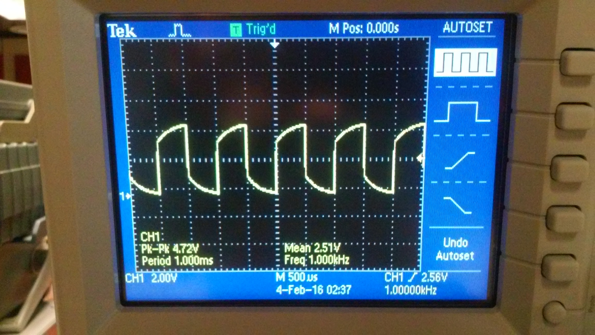 | 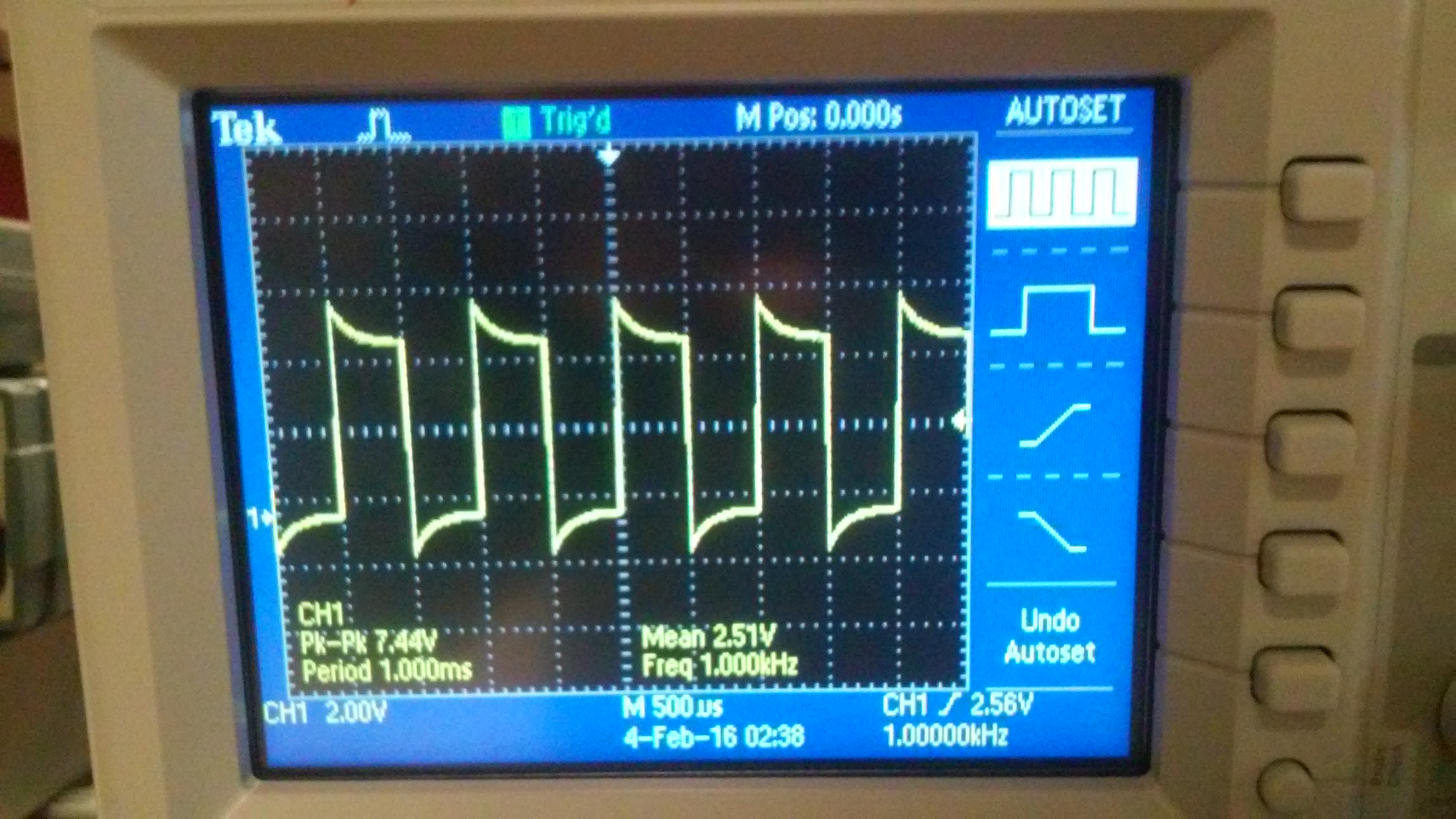 |  |
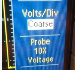
Scope probe setting
| Probe Comp ~5V@1kHz | Probe w/ switch from x1 (1:1) to x10 (10:1) | Probe attenuation setting (10x) |
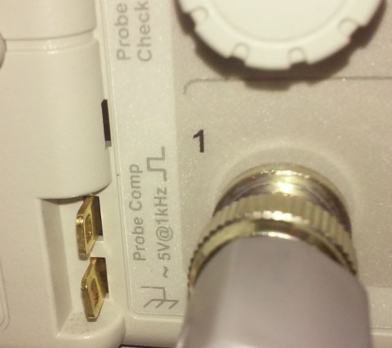 | 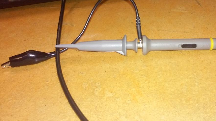 |  |
10:1 Scope probe schematic

Circuit Analysis of 10:1 scope probe


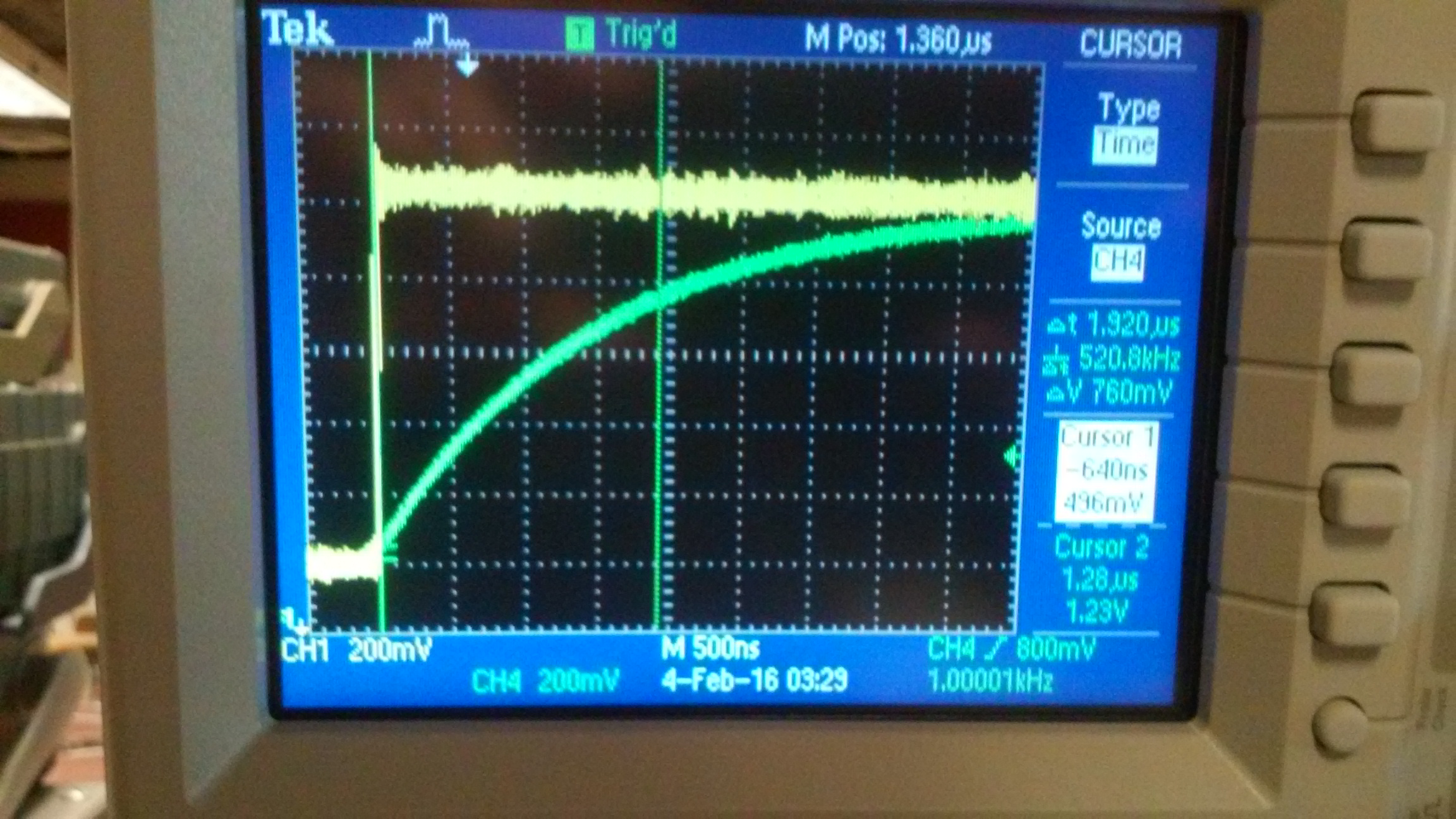
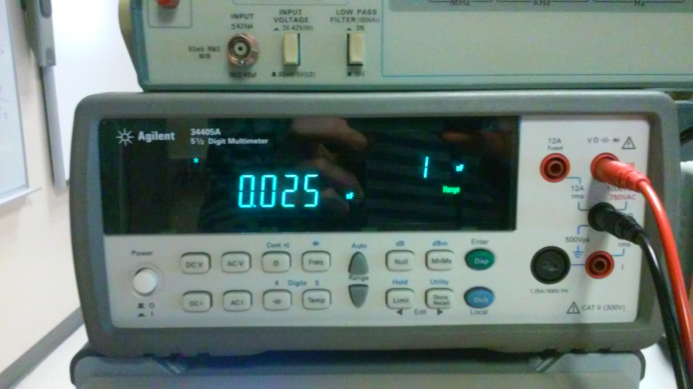
Measuring capacitance of a cable (~5ft)
| Square wave input vs squre wave output (resistor-cable circuit) (Delay time = 19.2us) | Measured capacitance of cable (25nF) |
 |  |
Hand Calculations

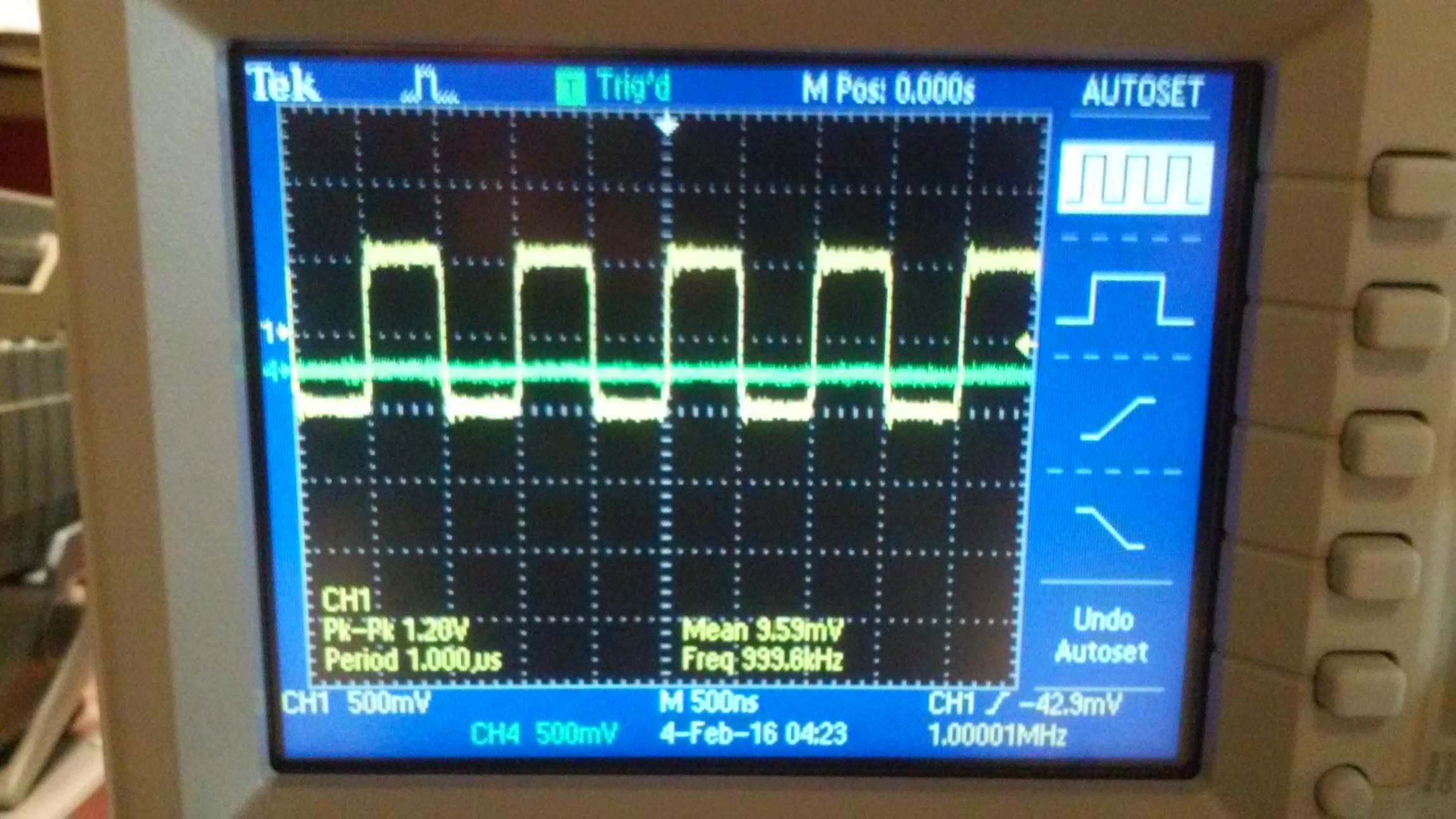
Measuring a 0-1V Square Wave 1MHz (Non-Compensated vs. Compensated)
Non-Compensated
We see a flat line at approximately 0.3 volts.
The large capacitance causes a large RC time constant.
The frequency is so fast that the capacitance can not fully discharge | Compensated
We see a charge and discharge signal around 0.3 volts.
The smaller capacitance causes a smaller RC time constant.
Although the frequency is fast, the small capacitance is able to dishcarge. |
 |  |
LTspice Simulation| Schematic | Simulation |
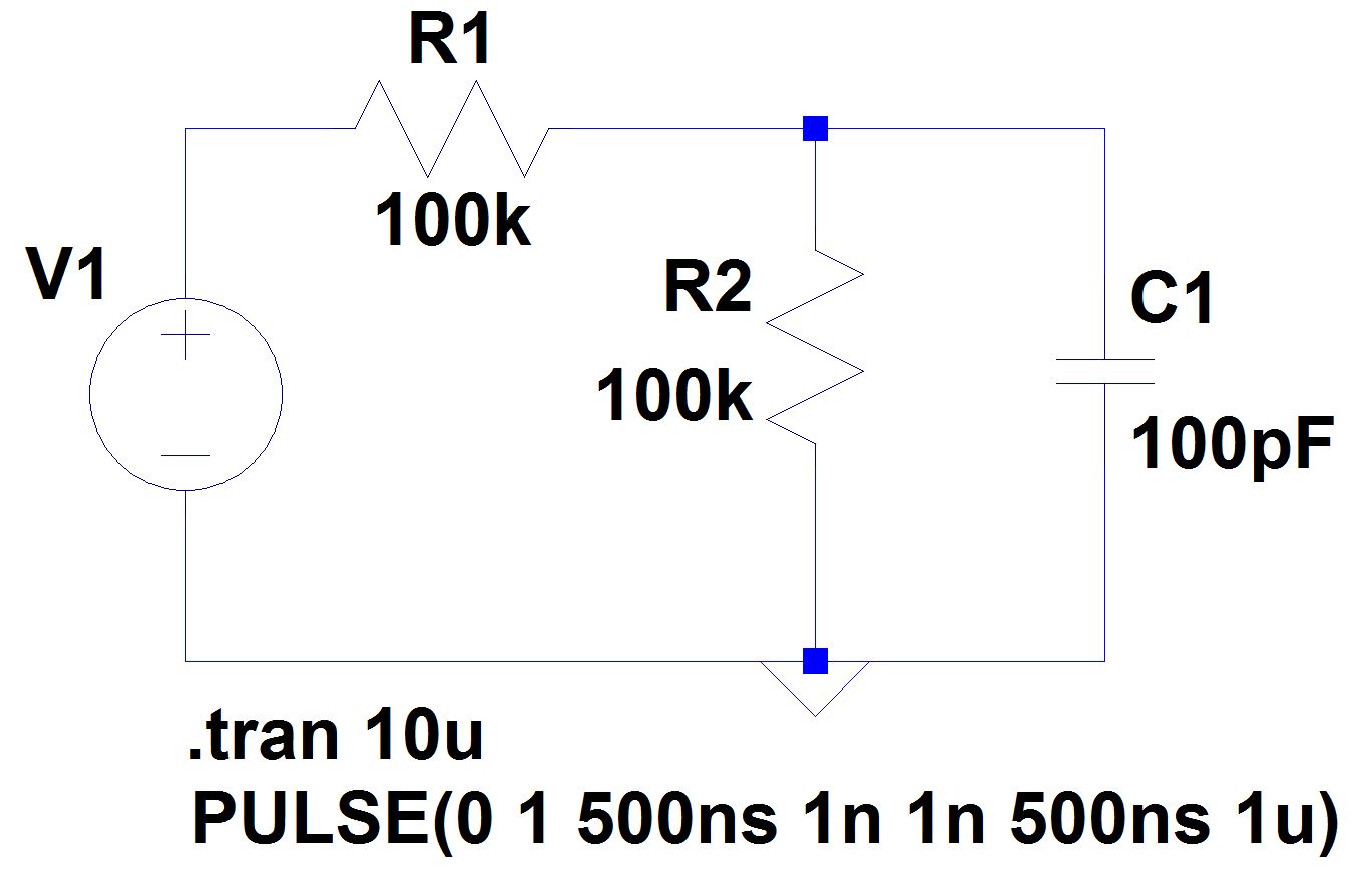 | 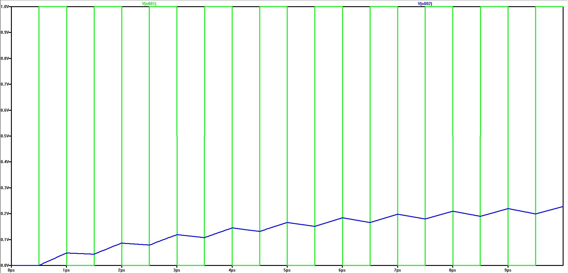 |
Implementing a PCB Test Point
It is important to include a capacitor (preferably variable) in
parrallel with the
sampling resistor of the test point when
designing a PCB board that will have coaxial cables directly connected
to it. This way, you can then fine tune the capacitor in parrallel with
the test point sampling resistor for compensation by connecting a known cable
length.
Conclusion
The
lab experiments performed reinforced knowledge of scope probes to
clearly understancd how to properly compensate a scope probe as well as
how the capacitance of a scope probe can influence circuit measurements
and performance.All experiments were performed without significant issues and resulted in expected and reasonable results.
Problems Encountered
Any
discrepancies between hand calculations, LTspice simulations, and
experimental results can mostly be attributed to the fact that I used a
110k resistor as opposed to 100k for all the experiments
performed.
Return to EE 420 Labs