EE
420L Engineering Electronics II Lab - Lab 7
Mario Valles
April 10, 2015
Vallesm@unlv.nevada.edu
Design of an audio
amplifier
Design an audio amplifier (frequency range from roughly 100 Hz to 20 kHz) assuming that you can use as many resistors, ZVN3306A transistors, and ZVP3306A transistors as you need along with only one 10 uF capacitor and one 100 uF capacitor. Assume that the supply voltage is 10 V, the input is an audio signal from an MP3 player (and so your amplifier should have at least a few kiloohms input resistance), and the output of your design is connected to an 8-ohm speaker (so, ideally, the output resistance of your amplifier is less than 1 ohm).
- Your lab report should detail your thoughts on the design of the amplifier including hand-calculations.
- A good place to start is with the push-pull amplifier characterized in lab 6.
- So what we did was to add a transistor at the output of the to get a better gain as the next picture shows:
- and got this results
- This compare to the calculations that we did were
- Vout/Vin = (gmn + gmp)(100k||8) = (260*8) = 2080
- The reason we did it like this is becuase leaving the push and pull amplifier by itself wasn't giving enough amplification to hear music, so we cascade another amplifier so we can multiply their gain.
- Build
and test your design.
- We builded and tested and data hard to read, we are no sure if its becuase is push and pull properties or because the oscilloscope here is the data for normal sinewave and music:
- With music:
- sinewave
- We increase the input voltage to hear the sound louder. We tried to add decople capacitors, it wouldn't help to get better readings. Also, by turning off the amplifier reading were normal, but as the amplifier was turn on even the closenes of the oscilloscope were affecting.
- Document the performance of the design including power dissipation, output swing, input resistance, output resistance.
- Since the input to the amplifier is at the transistor gates our input impedance was 100k
- Input resistance was
- we measure and got
- However even if we increase or decrease the input voltage or frequency the reading did not changed as much
- Output swing
- Was really difficult to read however base on the results were 1.02
- The output resistance
was the resistance of the speaker which we assumed 8 ohms and put a
8ohm resistance in series as in the input resistance. then meausing the
output resistance we got the following results, that show the output
resistance is about 8 ohms
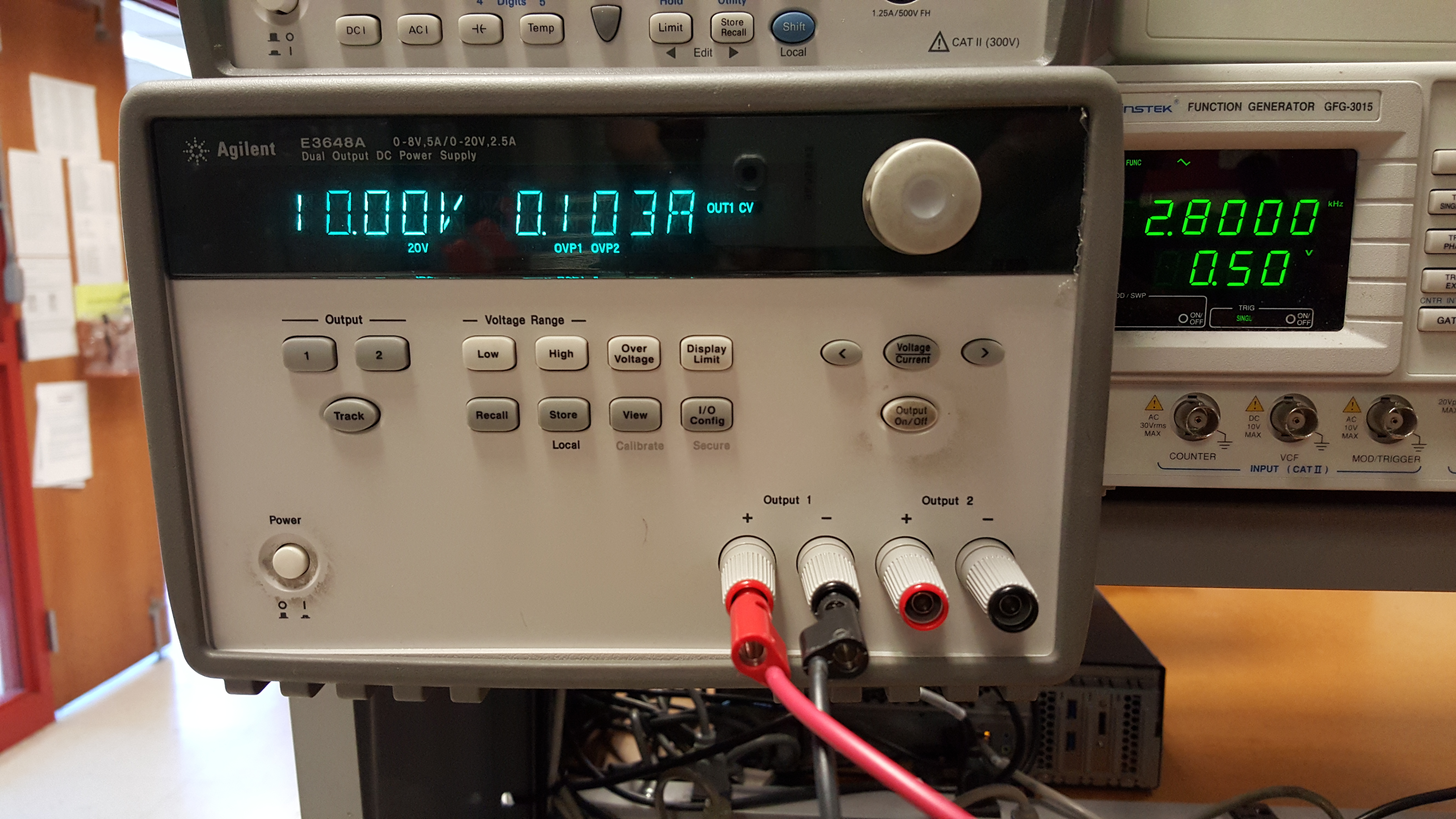
- Power dissipation was about 1.3W.

- The low output disiipation is becuase we go back in forth with adding and removing the source follower, however with source follower the current increases to more than 200 mA.
- The powever disippation was 2.83 W however we need to remove the source follower because it was getting hot and the rating were greater than the datasheet.