Lab 7- EE420L
Dwayne K. Thomas
4/10/2015
kendaleman@gmail.com
Design of an Audio Amplifier
The goal of this lab is to design an audio amplifier with as many
transistors and resistors as we need but only with the use of two
capacitors. The Amplifier will have a 10V supply voltage and
operate in the audible range from about 100Hz to 20kHz. The input
will be from an MP3 player therefore our amplifier should have at least
a few kiliohms of input reistance. But it must also have a small
output resistance in order to drive an 8-ohm speaker.
Circuit and Simulations
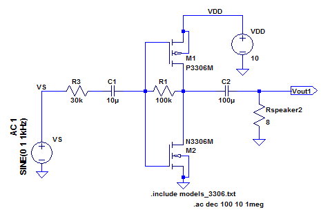 | Our amplifier Design in the schematic to the left makes use of the push-pull
amplifier which allows us to have a large gain for a minimal output
resistance with this type of transistor. We chose to only use two
transistors in our circuit in order to minimize the amperage through
our transistors which equates to less power dissipation |
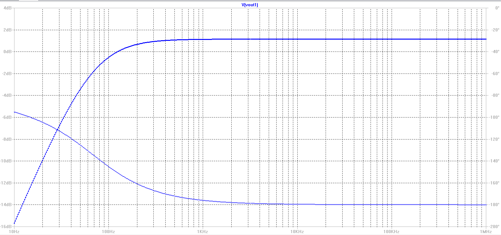 | The
Vout plots to the left show that for when we have a 1V signal on the
input of our amplifier, we get a small overall gain which is slightly
higer than our input. We were able to control the amount of gain
the amplifier gave us by manipulating R1 in the push-pull
configuration. In this particular case, we use an R1 of 100kohm.
The gain of the amplifier is calculated as:
id = vsg1 * (gm1) id = vgs2 * (gm2)
because vsg = vgs = vin
Vout/Vin = (R1)*(gm1 +gm2)
Vout/Vin = 100k * (.011 + .018)
Vout/Vin = 2900
But
because of the 30kohm resistor on the input, our gain total gain from
the mp3 player to our speaker ended up to be a little above 1.
|
 |
Power Dissipation
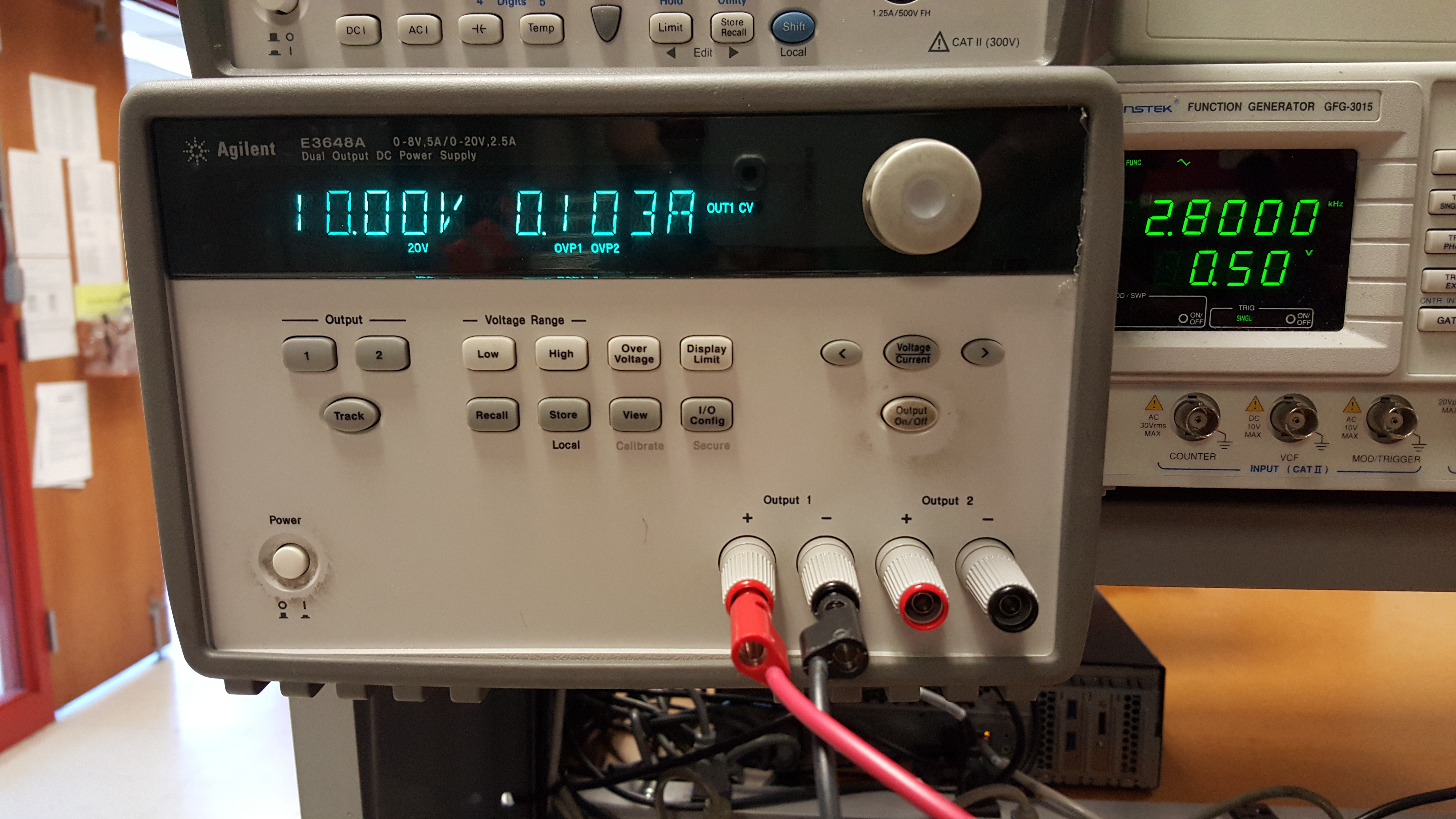 | The
supply output to the left shows us that for a 10V supply of VVD,
we have a total amperage draw of 103mA. This indicates that we
have only a 1 watt power dissipation due to there being no current
flowing through the 100k-ohm resistor.
In our original desingn, we
had another mosfet at the ouput of the push-pull amplifier to increase
our gain, but this addition caused too great of a power dissipation, so
we changed the circuit to our current two mosfet design. |
Input and Output Resistance
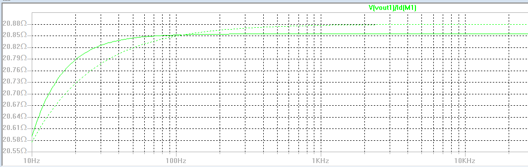 | The input resistance of the amplifier is 30kohm which we used to minimize the current drawn from the MP3 player.
The output resistance of the amplifier is 20kohms which is shown in the
plot to the left when the 8ohm speaker load is removed. With the 8ohm speaker load in place our output resistance becomes 8ohms. |
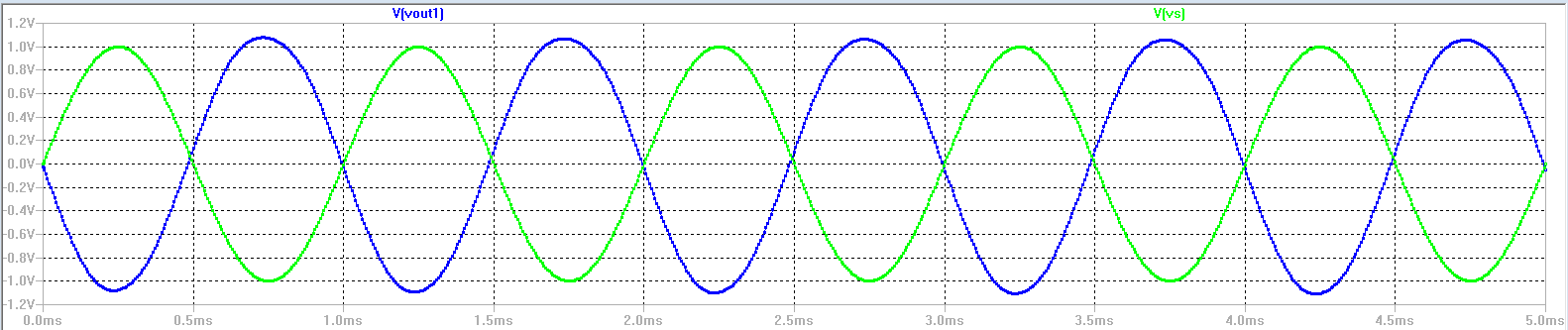
Output Swing
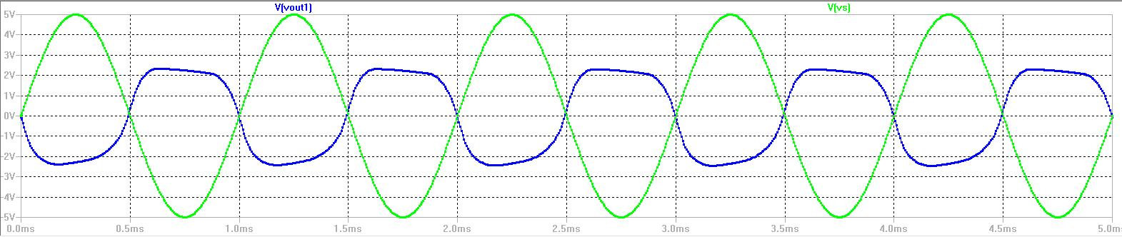 | The
graph to the left shows that our maximum output swing is between -2.5
and 2.5 volts. This shows us that our input voltage signal is
limited to an amplitude of 2V for our circuit design |
Return to EE420 labs