The purpose is this lab is to test the frequency
response of the Opamp integrator and use it to design
a triangle wave generator
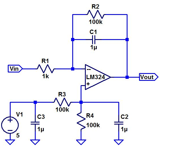
| Calculating the Frequency Response | |
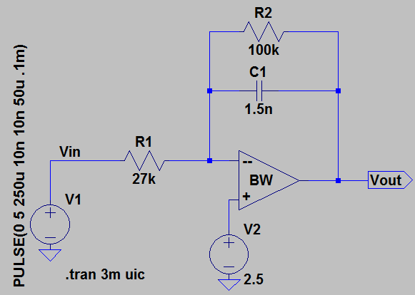
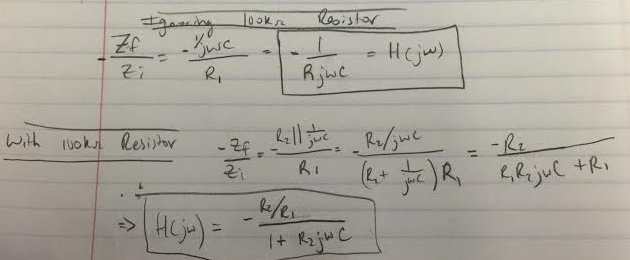 | We can neglect the 100KΩ feedback resistor in order to make our calculation easier. This is displayed in the first calculation on the left. The more complicated calculation is shown second which includes R2. |
| The circuit does not work if we remove the 100kΩ resistor because it is needed to feedback DC signals to the Opamp. The capacitor is an open to DC and will just charge once, causing the output to sit at either our positive rail of 5V or our negative rail of 0V. | The 100kΩ resistor does not have much effect on frequency response. This is especially at larger frequencies as seen in our frequency response calculation. The R2 change in the numerator will essentially cancel out the R2 change in the denominator. R2 is chosen to be large so that the AC current would go through the Capacitor and accomplish the task of integration. |
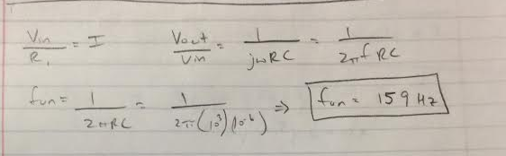
| The Unity Gain Plot below displays our input and output at the same amplitude. The Unity gain frequency was calculated to be 159Hz | |
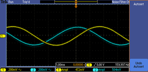 |  |
| Phase Shift Plot below | |
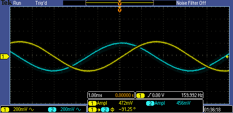 | The phase shift
between the input and output is as expected at 90 degrees. This is verified in the plot on the left. |
| Triangle Wave Generator | Simulated Plot |
 | 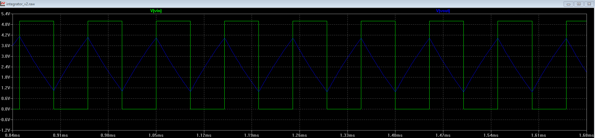 |
Building a circuit
that generates a triangle wave from a square wave wasn’t as easy as we
expected. Due to the operating frequency
of 10khz, Our period was calculated as 100microseconds.
| |
| By using a larger capacitor such as the 1-microFarad capacitor in the original circuit, too small of a resistor would need to be used and our gain was too big. | |
| If we used too small of a capacitor, the time constant of the resistor and capacitor come into play and gave us a curve in our triangle which we did not want. We had to find a capacitor somewhere in the middle that was not too small so as to not show this curve and not too large which would require a small input resistor that would give us too much gain. | |
| We were finally able to design the circuit using a 1.5nF capacitor and a 27kΩ resistor, which did not give us too much gain, and still was able to give the desired output. | |
| Calculations | 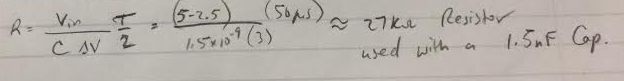 |
| Oscilloscope Output | 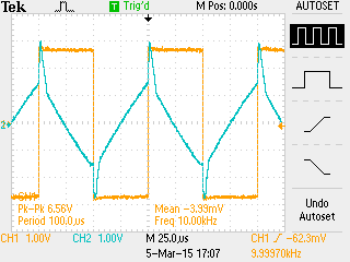 |