Lab 2 - EE 420L 

Dwayne K. Thomas

kendaleman@gmail.com

2/5/2015


Operation of a Compensated Scope Probe


    The Probes used in these labs, have an inherent capacitance due to the Probe tip as well as the cable attaching the probe to the scope.  Because of this, we need to calibrate our probes before we hook it up to our circuit so that we get our correct readings.  We use the 5V square wave calibration provided on the scope to accomplish this. The calibration screw we turn with a small (preferably plastic) flathead screw driver is either located at the probe head, or it can be located at the end of the cable with the coaxial conncection that hooks to our scope. Below is an example of an Overcompensated, undercompensated, and a correctly compensated probe.


    But before we calibrate the probe, we must tell the scope if our probe is set to 1X or 10X.  We will have to do this in the individual Channel menu our probe is connected to.  The scopes we use in this lab do not automatically sense the 1X or 10X.

http://cmosedu.com/jbaker/courses/ee420L/s15/students/thomad1/Lab2/overcompensated%20probe.JPG
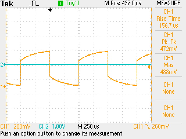
This is the scope reading of an Overcompensated probe
http://cmosedu.com/jbaker/courses/ee420L/s15/students/thomad1/Lab2/undercompensated%20probe.JPG
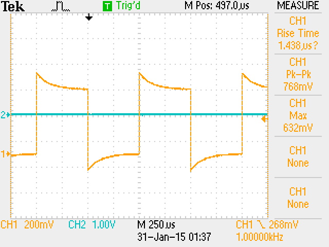
This is the scope reading of an Undercompensated probe
http://cmosedu.com/jbaker/courses/ee420L/s15/students/thomad1/Lab2/comp%20probe.JPG
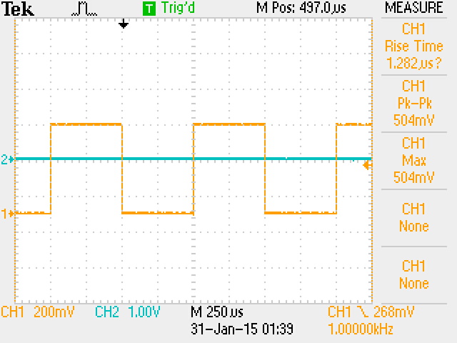
This is the scope reading of a Correctly Compensated probe

The 10:1 ratio for a probe

    The following schematic and calculations show how we get a 10:1 ratio for Vout/Vin when we have 9Megohm resistor in parallel with an about 12pF capacitor for the probe tip.  This combined impedance which we will call Z1 is the impedance of the probe tip.  The cable along with the connector to the scope has a combined capacitance of about 110pF which is in parallel with the input resistance of the scope which is 1Megohm.  We will call this impedance Z2.  The calculations show that Vout/Vin ~ 0.1

http://cmosedu.com/jbaker/courses/ee420L/s15/students/thomad1/Lab2/Probe%20Schematic.PNG
http://cmosedu.com/jbaker/courses/ee420L/s15/students/thomad1/Lab2/Probe%20calc1.PNGhttp://cmosedu.com/jbaker/courses/ee420L/s15/students/thomad1/Lab2/Probe%20calc2.PNG

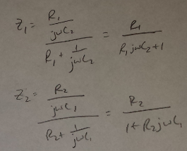
Capacitance of a 3-foot wire Experiment

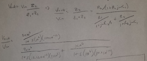
    The following is an experiment performed in order to determine the capacitance of a 3-foot wire by measuring the phase shift displayed on our scope.

http://cmosedu.com/jbaker/courses/ee420L/s15/students/thomad1/Lab2/cable%20capacitance.JPG
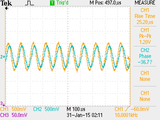
As we can see, the phase shift measured with our scope shows us a 36.7 degree shift.
http://cmosedu.com/jbaker/courses/ee420L/s15/students/thomad1/Lab2/Measured%20Capacitance%20of%20wire.jpg
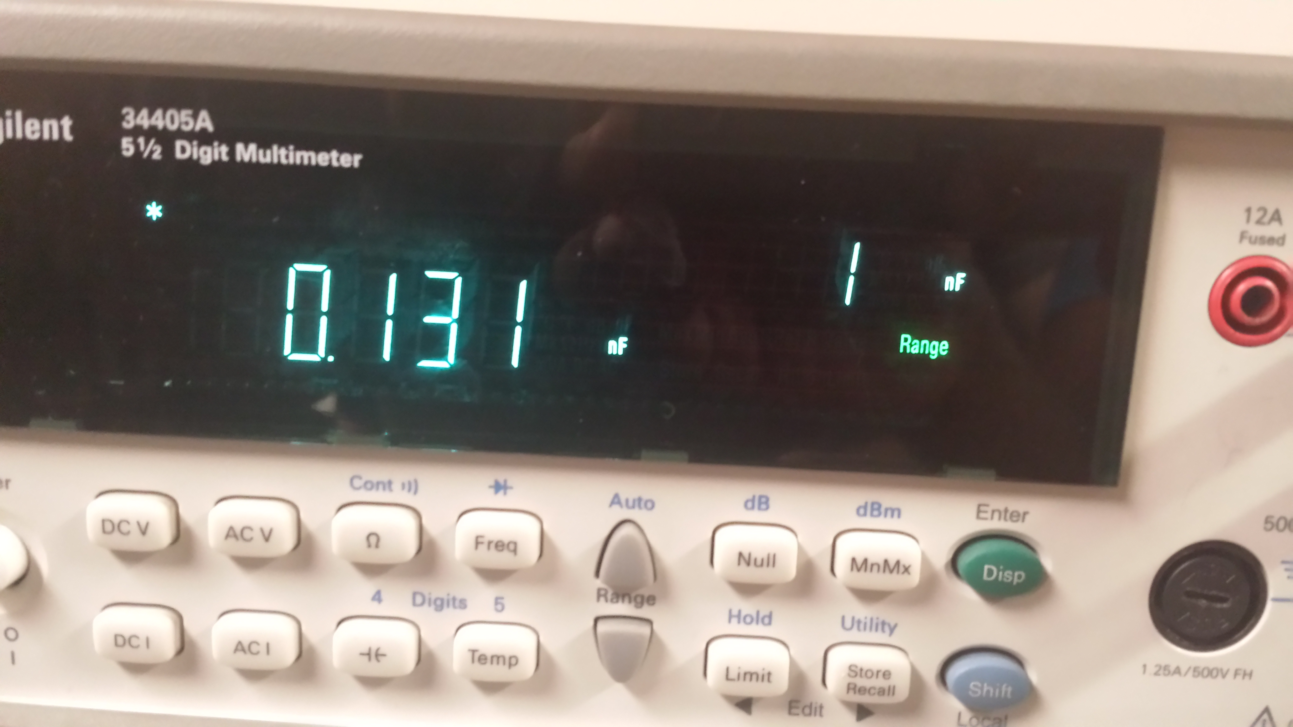
When we measured the capacitance of the 3-foot wire, we received 131pF.
This is close to our calculated Capacitance of 114pF.
http://cmosedu.com/jbaker/courses/ee420L/s15/students/thomad1/Lab2/cablecapcalc.jpg
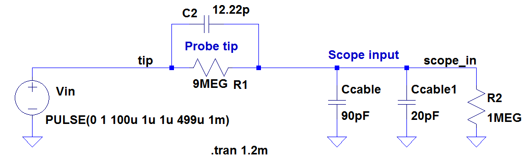
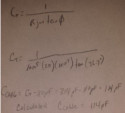
By wiring the 3-foot cable in parallel with our probe tip, and all in series with a 100kohm resistor, our total Capacitance is the sum of the 110pF of the probe, and  the cable.


Voltage Divider with 100Kohm Resistors

    In this experiment, we show that uncompensated probes can significantly affect the measurement results of our circuit due to the loading effects of our measuring device.  We accomplish this by building a voltage divider and measuring first with just a 3-foot cable and then with a compensated probe.

http://cmosedu.com/jbaker/courses/ee420L/s15/students/thomad1/Lab2/cable%20v-divider.JPGhttp://cmosedu.com/jbaker/courses/ee420L/s15/students/thomad1/Lab2/compensated%20voltage%20divider.JPG
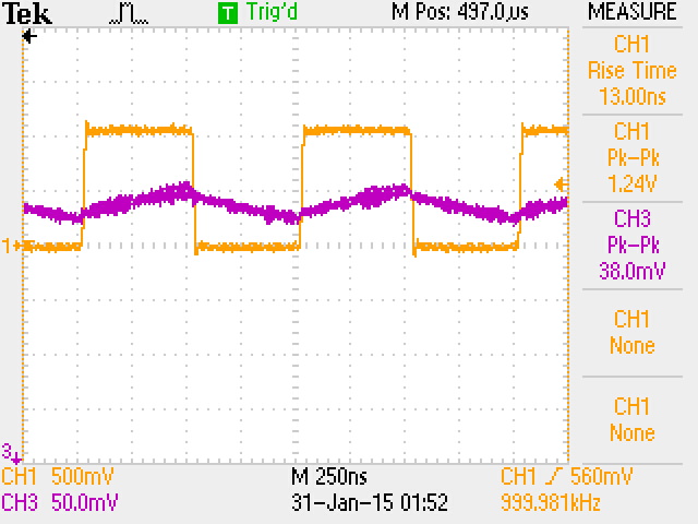
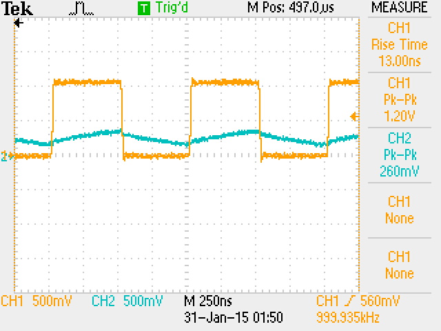
The output voltage from the Uncompensated probe shows our pk-pk voltage at 38mVThe output voltage from the compensated probe shows our pk-pk voltage at 260mV.  A much a higher reading from the uncompensated probing.


Return to EE420 labs