Lab 1 - EE 420L 

Dwayne K. Thomas

kendaleman@gmail.com

January 29, 2015


Review of basic RC circuits


Experiment 1
Figure 1.21
 

ftp://cmosedu.com/lab1/1.21%20schematic.PNGhttp://cmosedu.com/jbaker/courses/ee420L/s15/students/thomad1/Lab1/1.21%20schematic.PNG    http://cmosedu.com/jbaker/courses/ee420L/s15/students/thomad1/Lab1/lab1%20calculations.PNG

This is a simple RC circuit that has a phase shift of -51.5 degrees based off of the values chosen for the Resistor and Capacitor.

Below are the hand calculations, and a plot of the output showing Vin and its comparison to Vout

http://cmosedu.com/jbaker/courses/ee420L/s15/students/thomad1/Lab1/1.21%20plot.PNG

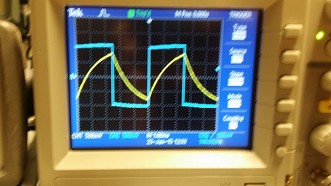
Shown to the right is the output of our Oscilloscope after we built the circuithttp://cmosedu.com/jbaker/courses/ee420L/s15/students/thomad1/Lab1/1.21%20scope.BMP

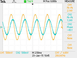
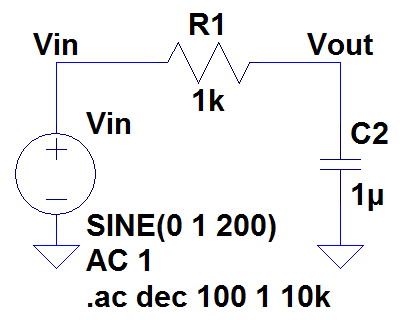
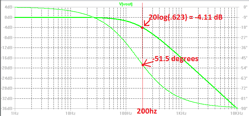
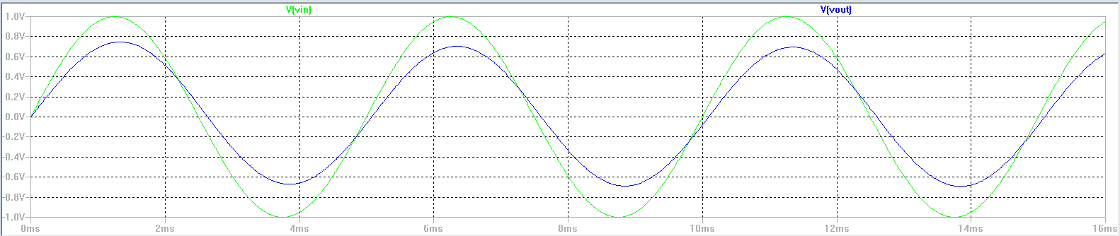
Figure 1.23 below is associated with the figure 1.21 circuit of Experiment 1.  Its shows bode plot for the circuit in experiment 1

http://cmosedu.com/jbaker/courses/ee420L/s15/students/thomad1/Lab1/1.23%20schematic.PNGhttp://cmosedu.com/jbaker/courses/ee420L/s15/students/thomad1/Lab1/1.23%20plot.PNG


Experiment 2

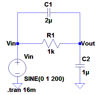
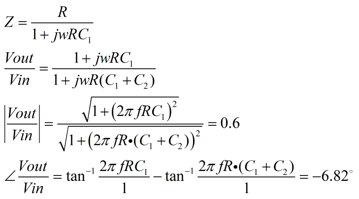
In Experiment 2, we add a 2uF capacitor in parallel with the Resistor which gives us a phase correction, making the phase shift smaller than we acquired in Experiment 1.

http://cmosedu.com/jbaker/courses/ee420L/s15/students/thomad1/Lab1/1.22%20schematic.PNGhttp://cmosedu.com/jbaker/courses/ee420L/s15/students/thomad1/Lab1/Lab1%20calculations2.PNG

http://cmosedu.com/jbaker/courses/ee420L/s15/students/thomad1/Lab1/1.22%20scope.png

http://cmosedu.com/jbaker/courses/ee420L/s15/students/thomad1/Lab1/1.22%20plot.PNG

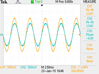
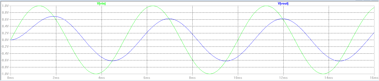
Our oscilloscope plot for this experiment matches what we simulated in SPICEhttp://cmosedu.com/jbaker/courses/ee420L/s15/students/thomad1/Lab1/1.22%20scope.png


Experiment 3

Experiment 3 shows what our output would be if we had a square wave input.  Showing that our output resembles more of a sawtooth wave with this type of circuit.
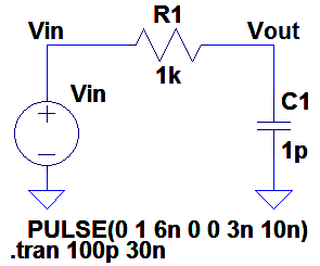
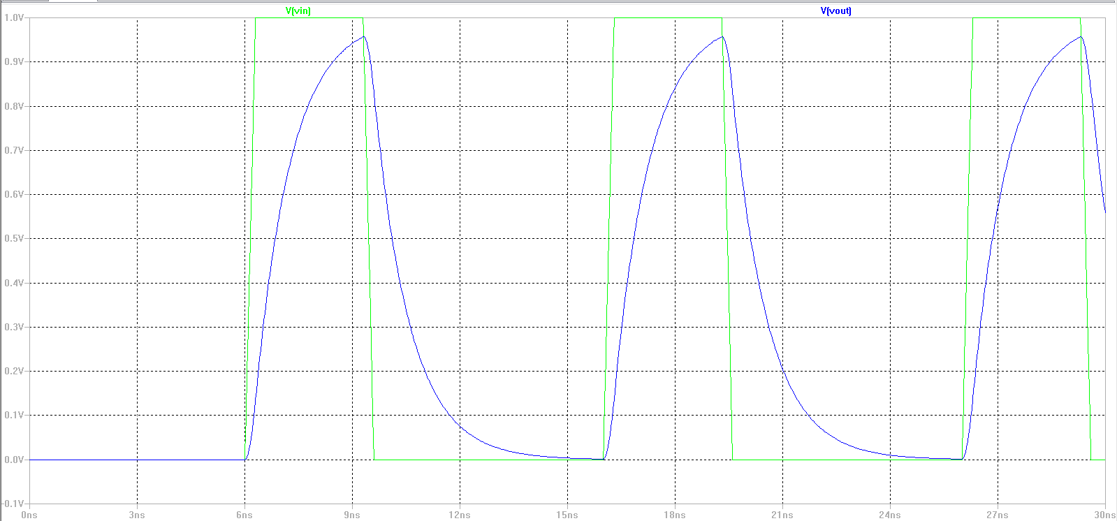
http://cmosedu.com/jbaker/courses/ee420L/s15/students/thomad1/Lab1/1.24%20schematic.PNG

http://cmosedu.com/jbaker/courses/ee420L/s15/students/thomad1/Lab1/1.24%20plot.PNG

The output on our Oscilloscope for the sawtooth came out bettter than our simulation results due to us using a 1uF capacitor instead of a 1pF.http://cmosedu.com/jbaker/courses/ee420L/s15/students/thomad1/Lab1/1.24%20scope.png

Return to EE420 labs