EE 420L - Lab 6
Single-stage transistor amplifiers
This lab will utilize the ZVN3306A and ZVP3306A MOSFETs.
Experiment 1: Common Drain (CD) amplifiers
CD NMOS and PMOS amplifiers
Operation
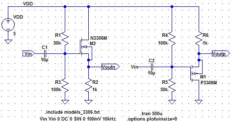
A Common Drain amplifier is DC biased such that the NMOS and PMOS are operating in saturation. Input is supplied through the gateand output is measure at the source. Drain is tied to VDD which in AC is 0v and this is why is is called Common Drain.
Common Drain amplifiers are also called source followers because the gain is often very close to one and no phase shift occurs during amplification thus our input at the gate is almost identical to the output at the source.
Simulations
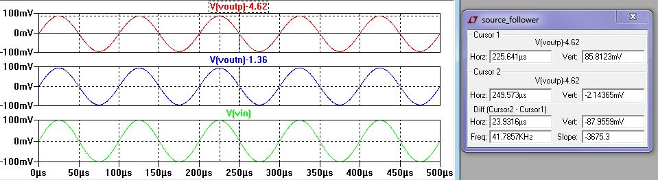
Green: Vin, Red: PMOS Vout, Blue: NMOS Vout
Note: In this lab, we connect the electrolytic capacitor (+) lead to the gate node and the (-) lead to the input node because the gate node has more voltage than the input node. The gate node has a DC offset provided by the voltage divider circuit while the input node has 0v DC with a small AC voltage.
Input and Output Resistances
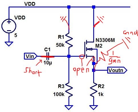
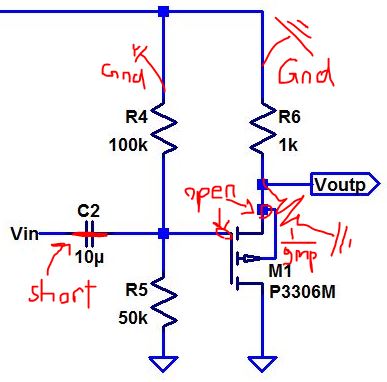
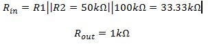
CD NMOS Amplifier Input and Output Resistances CD PMOS Amplifier Input and Output Resistances
Input and output resistance calculation
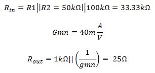
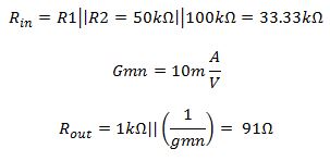
NMOS PMOS
Note: Output resistance includes 1/gmn because 1/gmn is associated with the source node. Also the gmn and gmp value is estimated and not measured.
NMOS Input Resistance PMOS Input Resistance
Gain:
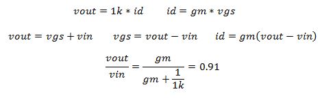
Gain Calculation:
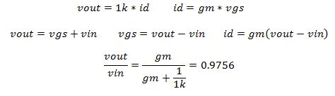
NMOS
PMOS
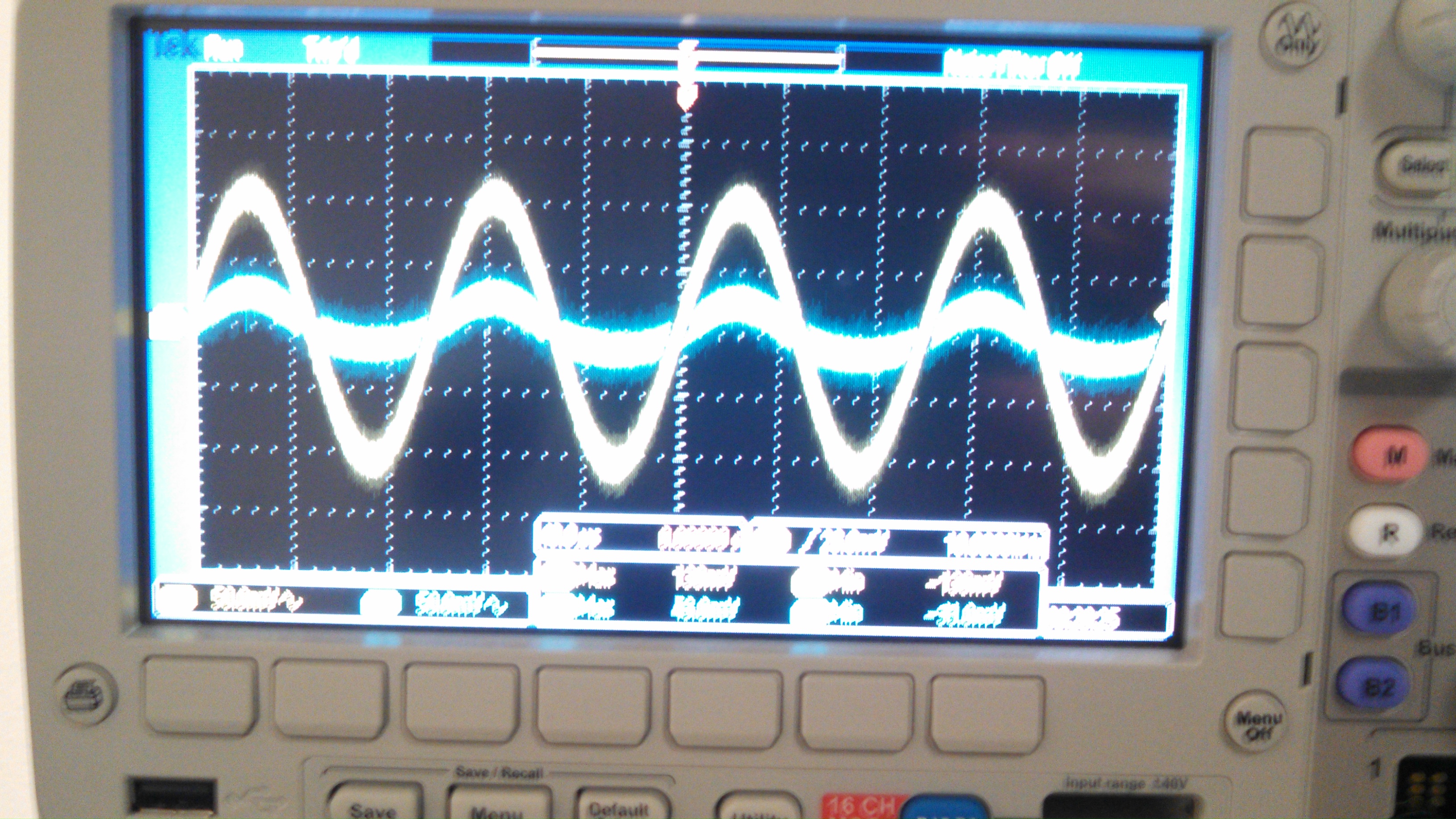
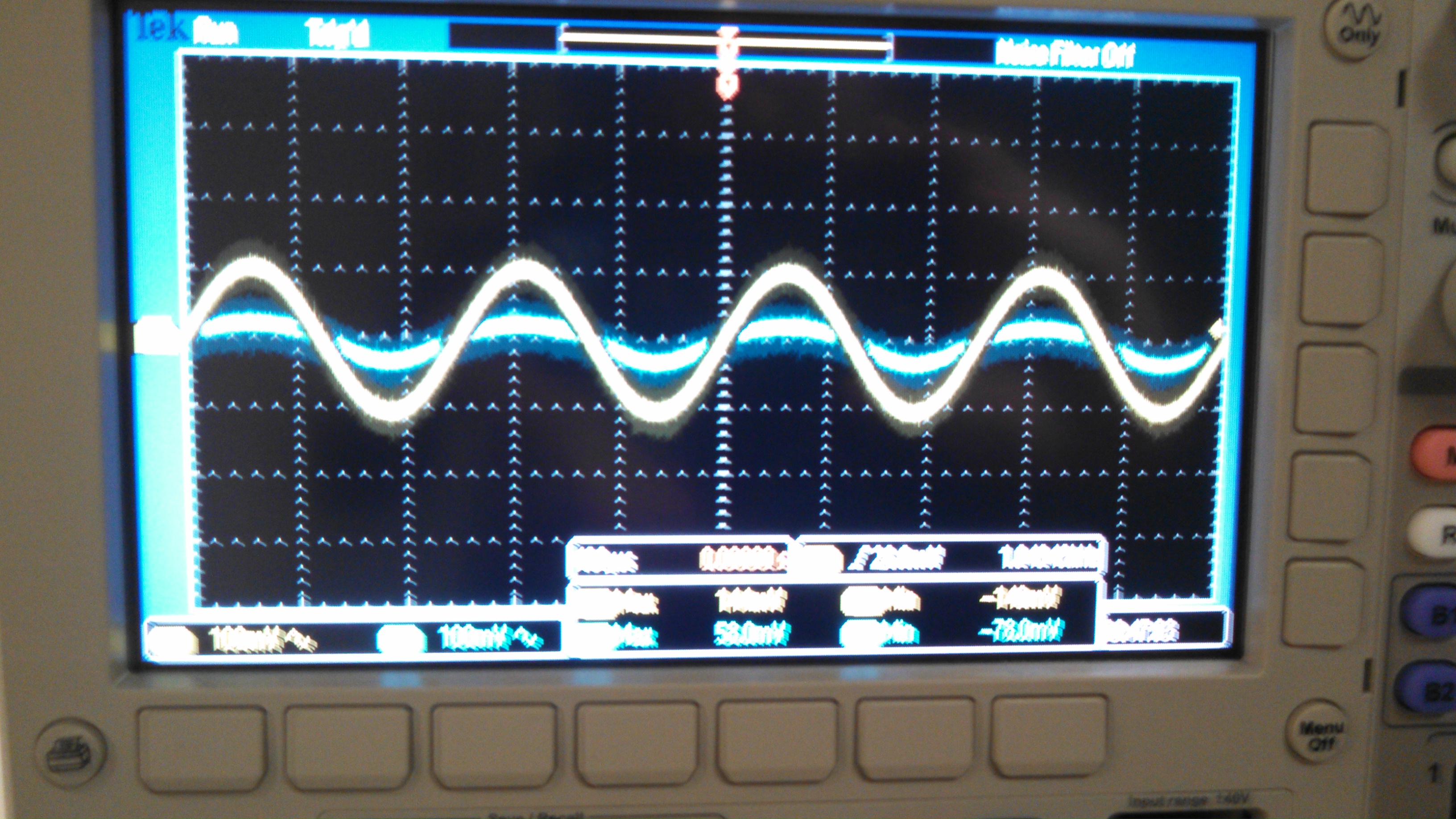
NMOS Gain PMOS Gain
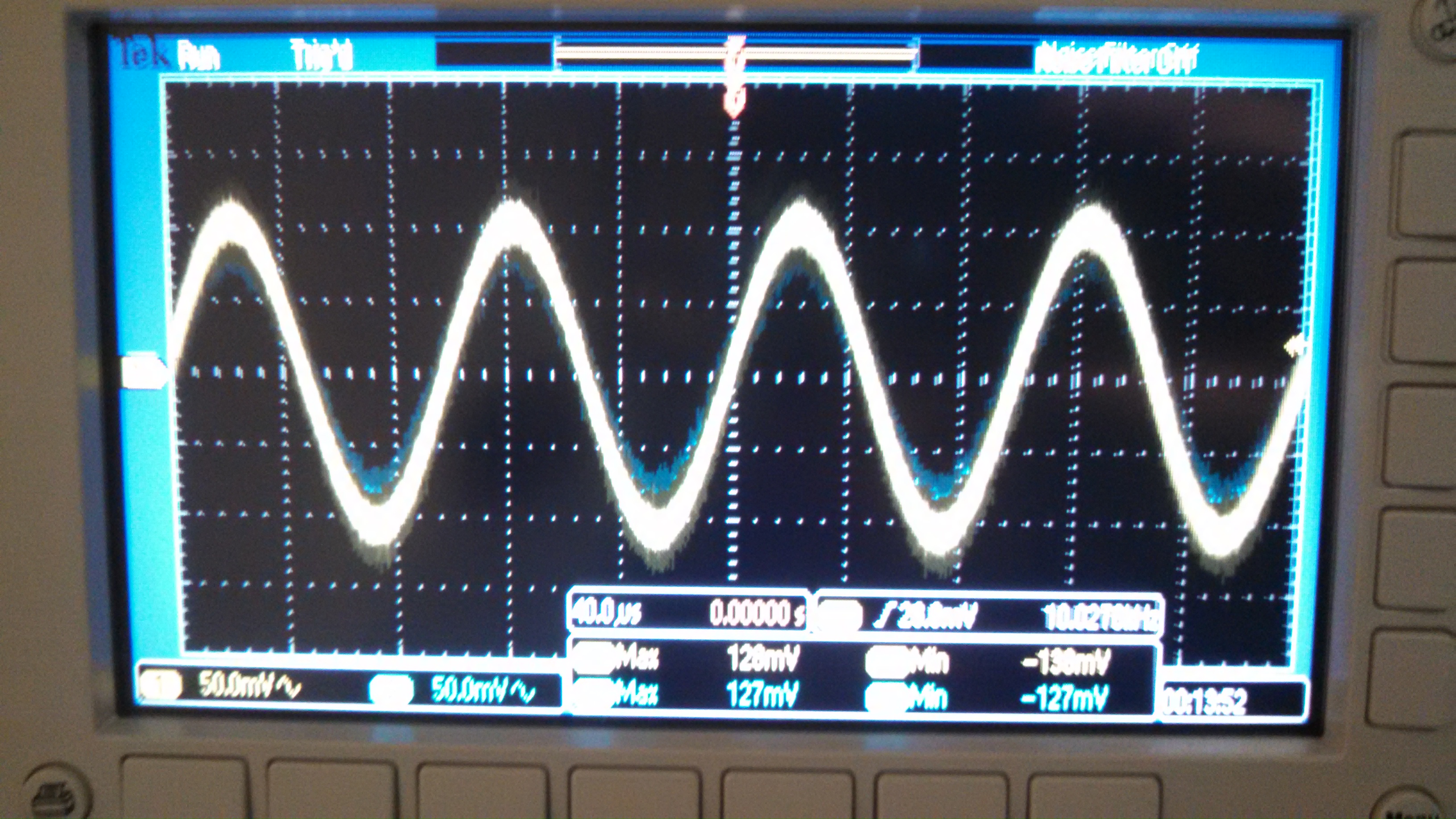
Measured results of the gain, yellow is input, blue is output. As to be expected, it is a gain of 1 and with no phase shift.
Table
| NMOS | Calculated Results | Simulated Results | Measured Results |
| Input Resistance | 33.33k | N/A | 33.33k |
| Output Resistance | 24.39 | N/A | 267.3 |
| Gain | 0.9756 | 0.8581 | 0.927 |
| PMOS | Calculated Results | Simulated Results | Measured Results |
| Input Resistance | 33.33k | N/A | 33.33k |
| Output Resistance | 90.9 | N/A | 180.4 |
| Gain | 0.91 | 0.8588 | 0.808 |
Experiment 2: Common Source CS Amplifiers
CD NMOS and PMOS amplifiers
Operation
A Common Source amplifier is DC biased such that the NMOS and PMOS are operating in saturation. Input is supplied through the gate and output is measure at the Drain. This amplifer produces high giain due to the parallel resistance at the source node. The output also sees a phase shift of 180 degrees.
Simulations
Green: Vin, Red: PMOS Vout, NMOS Vout
Note: In this lab, we connect the electrolytic capacitor (+) lead to the gate node and the (-) lead to the input node because the gate node has more voltage than the input node. The gate node has a DC offset provided by the voltage divider circuit while the input node has 0v DC with a small AC voltage.
Input and Output Resistances
CS NMOS Amplifier Input and Output Resistances CS PMOS Amplifier Input and Output Resistances
Input and output resistance calculation
Note: Output resistance does not include 1/gmn because 1/gmn is associated with the source node. Also the gmn and gmp value is estimated and not measured. We only include one calculation here because it is the same for NMOS and PMOS.
Gain:
Gain Calculation:
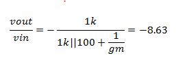
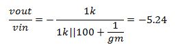
NMOS PMOS
NMOS PMOS
Table
| NMOS | Calculated Results | Simulated Results | Measured Results |
| Input Resistance | 33.33k | N/A | 33.33k |
| Output Resistance | 1k | N/A | 1k |
| Gain | -8.63 | -5.33 | -7.33 |
| PMOS | Calculated Results | Simulated Results | Measured Results |
| Input Resistance | 33.33k | N/A | 33.33k |
| Output Resistance | 1k | N/A | 1k |
| Gain | -5.23 | -6.94 | -5.25 |
Experiment 3: Common Drain (CG) amplifiers
CG NMOS and PMOS amplifiers
Operation
A Common Gate amplifier is DC biased such that the NMOS and PMOS are operating in saturation. Input is supplied through the source and output is measure at the drain. The common gate amplifier also sees high gain but this time no phase shift occurs.
Simulations
Green: Vin, Red: PMOS Vout, Blue: NMOS Vout
Note: In this lab, we connect the electrolytic capacitor (+) lead to the gate node and the (-) lead to the input node because the gate node has more voltage than the input node. The gate node has a DC offset provided by the voltage divider circuit while the input node has 0v DC with a small AC voltage.
Input and Output Resistances
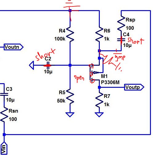
CG NMOS Amplifier Input and Output Resistances CG PMOS Amplifier Input and Output Resistances
Input and output resistance calculation
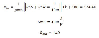
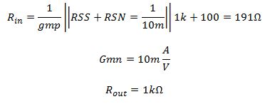
NMOS PMOS
Note: Output resistance includes 1/gmn because 1/gmn is associated with the source node. Also the gmn and gmp value is estimated and not measured.
Gain:
Gain Calculation:
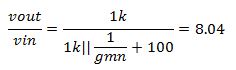
NMOS
PMOS
NMOS Gain PMOS Gain
Table
| NMOS | Calculated Results | Simulated Results | Measured Results |
| Input Resistance | 124.4 | N/A | 166.5 |
| Output Resistance | 1k | N/A | 1.325k |
| Gain | 8.04 | 6.22 | 6.5 |
| PMOS | Calculated Results | Simulated Results | Measured Results |
| Input Resistance | 191 | N/A | 275 |
| Output Resistance | 1k | N/A | 1.25k |
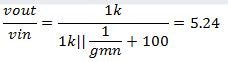
| Gain | 5.24 | 4.77 | 5.1 |
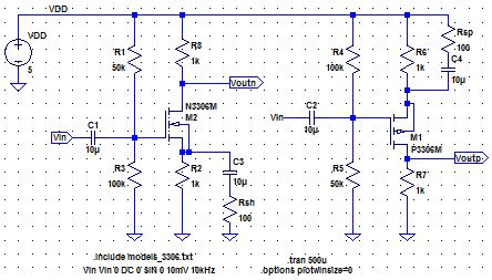
Experiment 4: Push-pull Amplifier
Operation: The push-pull amplifier works as a AB Class amplifier, meaning that different parts of the transistors can be on at a time. Also, the DC operation depends on the inout voltage. For the AB class amplifier, the NMOS and PMOS will be activated at different situations; if the inout voltage is low, the NMOS will turn off and the PMOS will turn on, but if the input voltage is high, the PMOS will turn off and the NMOS will turn on. When the PMOS is on, the amplifier sources current from VDD to Vout and when the NMOS is on, it will sink current from Vout to ground. The circuit is naturally good at sourcing and sinking current bacuase it uses both a PMOS to source and an NMOS to sink current.
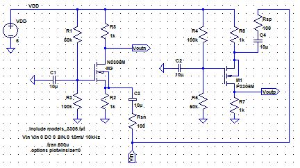
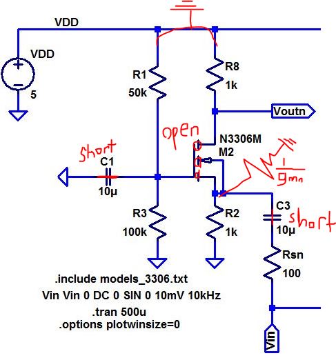
Schematic
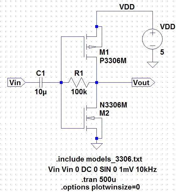
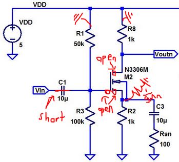
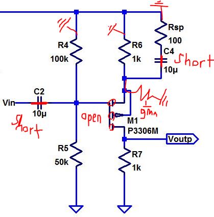
Calculations
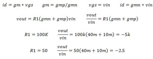
When R1 = 100k, our simulations clipped too hard to see accurate results so we had to use a 50 ohm resistor to get actual results that we could measure.
Given our gain calculations, if we replace our 100k resistor with 510k, we expect the gain to increase to 25.5k and we also expect our signal to clip, heavily.
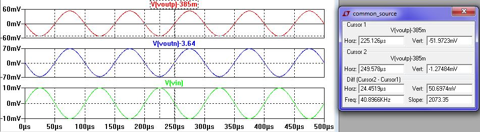
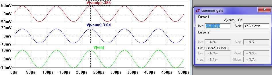
Simulations
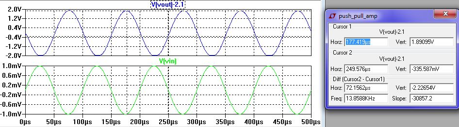
R1=100K, Gain=-3780
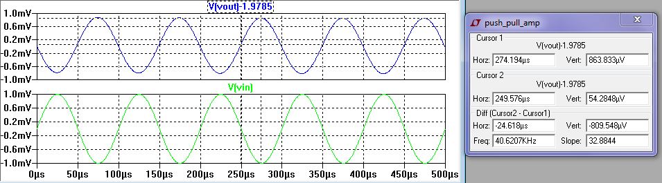
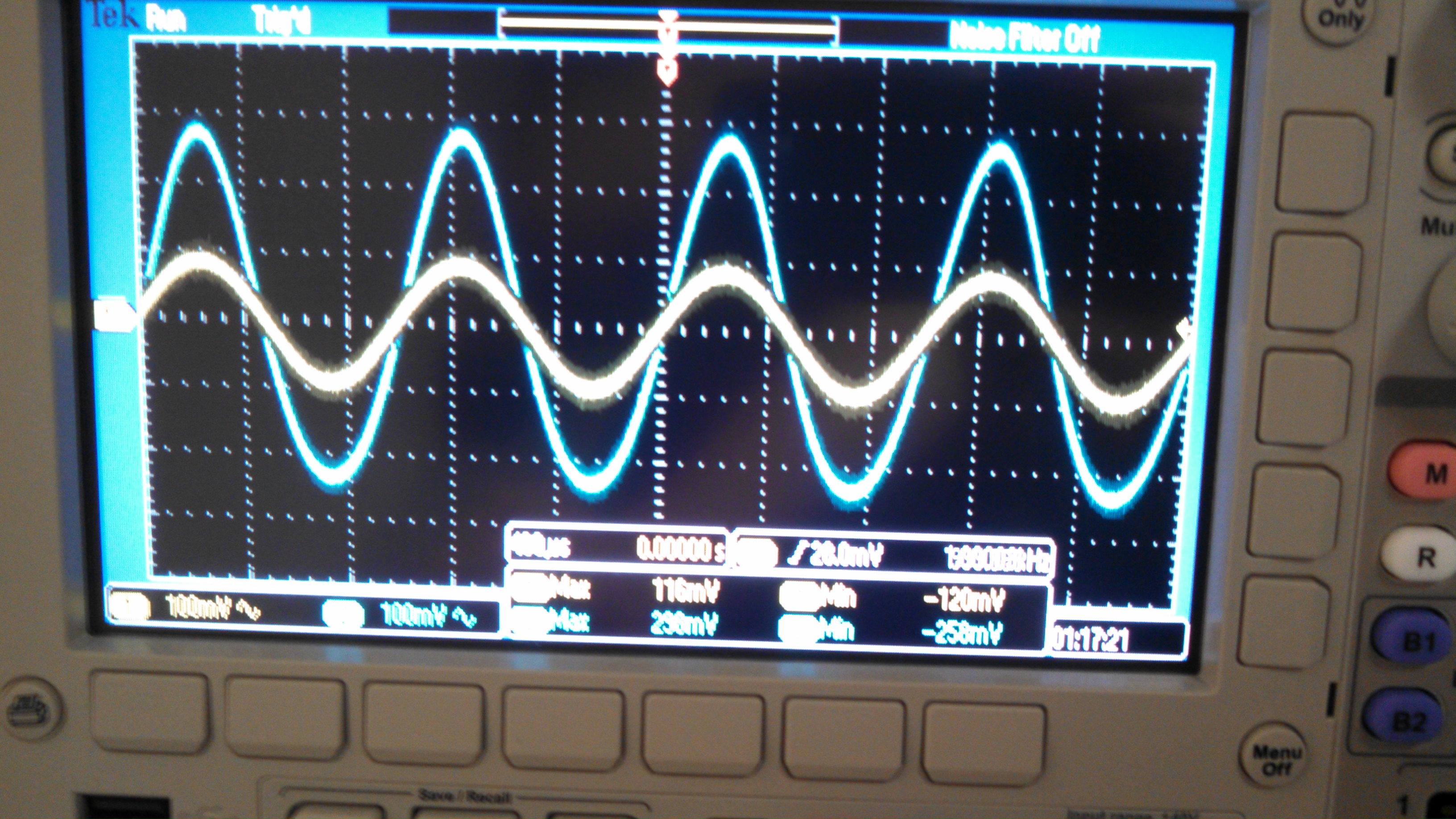
R1=50, Gain=-0.864
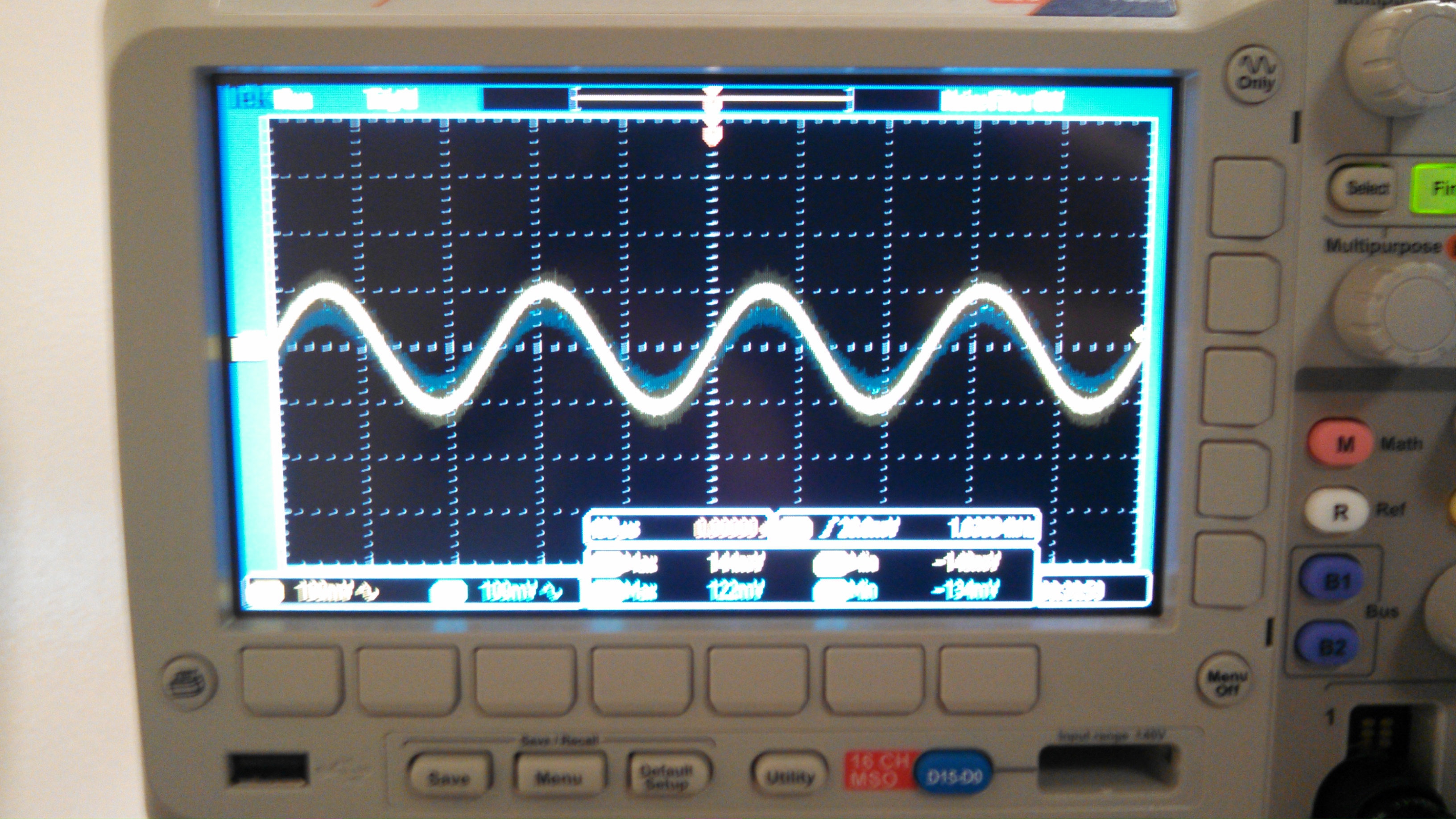
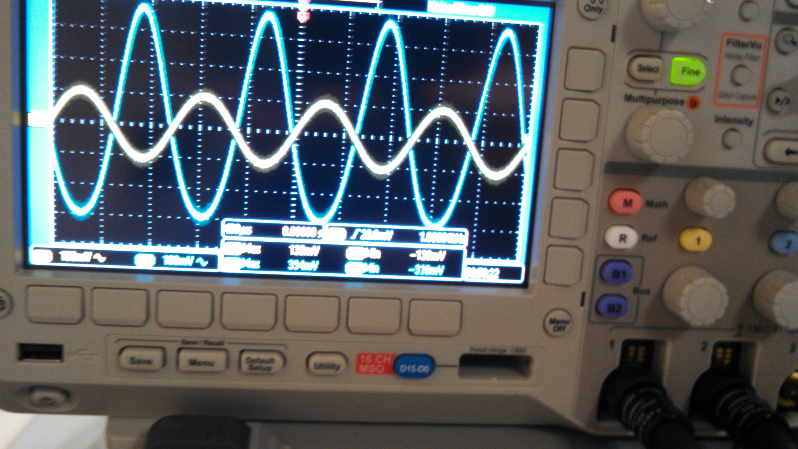
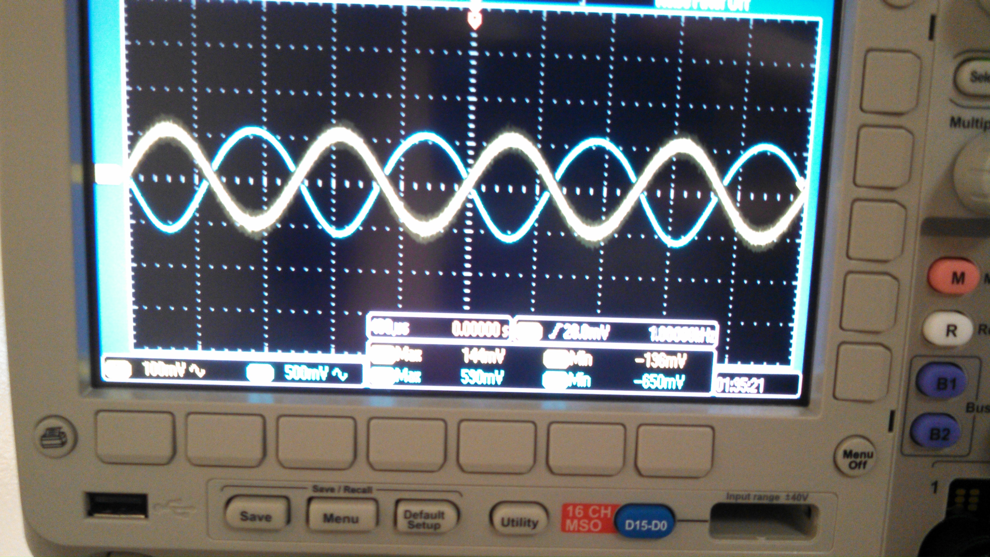
Scope
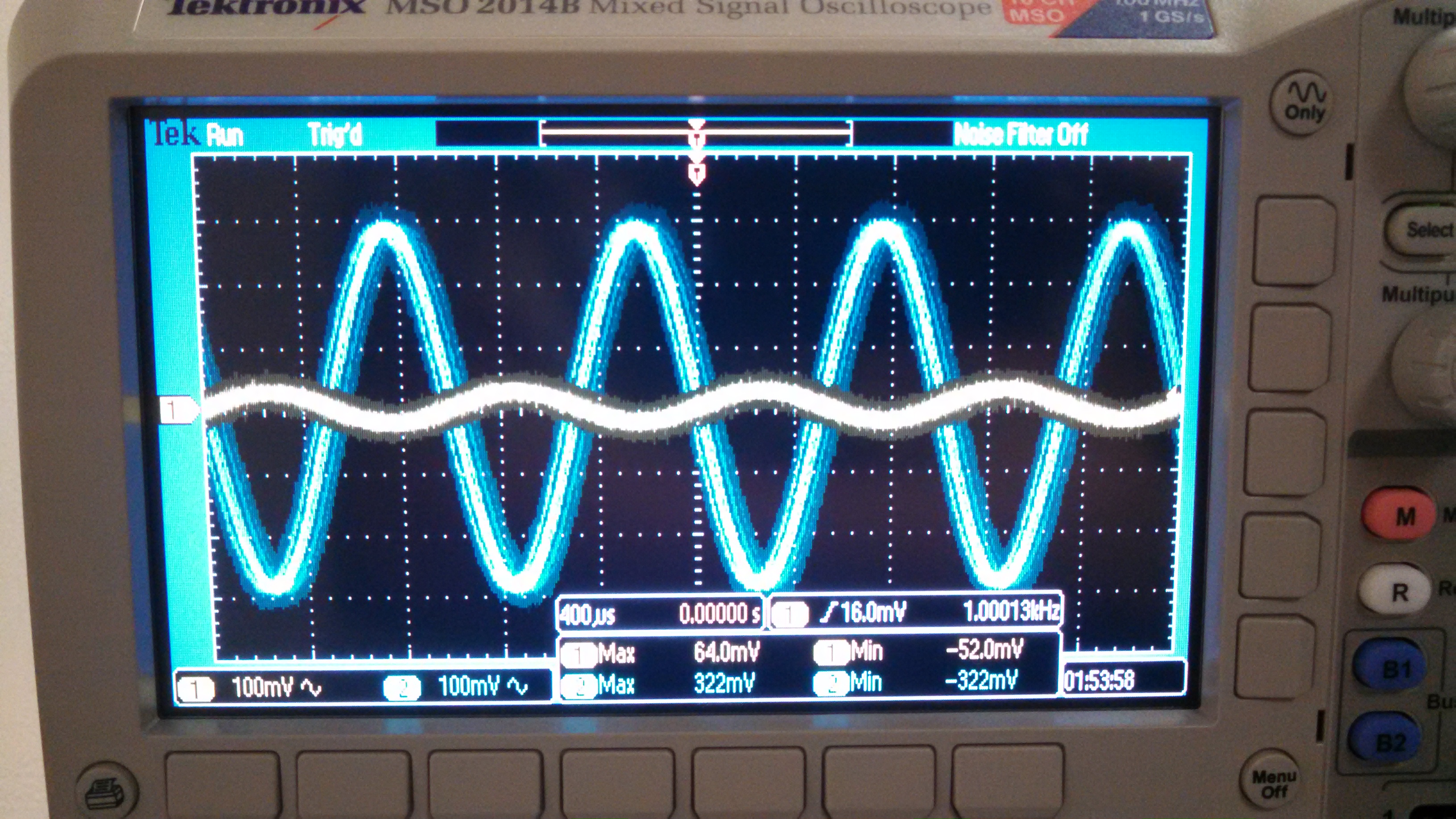
Gain with R1 = 50
Table
| Push-Pull Amplifier | Calculated Results | Simulated Results | Measured Results |
| Gain | -2.5 | -0.864 | -5 |