EE 420L - Lab 4
Op-amps II, gain-bandwidth product and slewing
(Q) Estimate, using the datasheet, the bandwidths for non-inverting op-amp topologies having gains of 1, 5, and 10.
(A) We can calculate a bandwidth given a gain in two ways:
Gain 1:
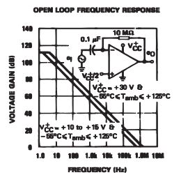
1) First, we may look at the Open Loop Frequency Response graph and, given our gain, we may trace an approximation of our bandwidth. A gain of 1 V/V equates to 0 dB making our bandwidth about 1MHz.
2) A second way of calculating our bandwidth is to use our Wide Gain Bandwidth equation:
Gain Bandwidth = Gain x Frequency
Thus, if our Wide Gain Bandwidth is 1.3MHz, and our gain is 1 V/V, we can say:
1.3M = 1 x f
which of course means:
f = 1.3MHz
Gain 5:
1) A gain of 5 V/V translates to about 14 dB, which we can trace to a frequency of about 300kHz.
2) Using the Gain Bandwidth equation, we calculate a bandwidth frequency of about 260kHz.
Gain 10:
1) A gain of 10 V/V translates to about 20 dB, which we can trace to a frequency of about 100kHz.
2) Using the Gain Bandwidth equation, we calculate a bandwidth frequency of about 130kHz.
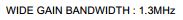
(Q) Experimentally verify these estimates assuming a common-mode voltage of 2.5 V.
Gain 1:
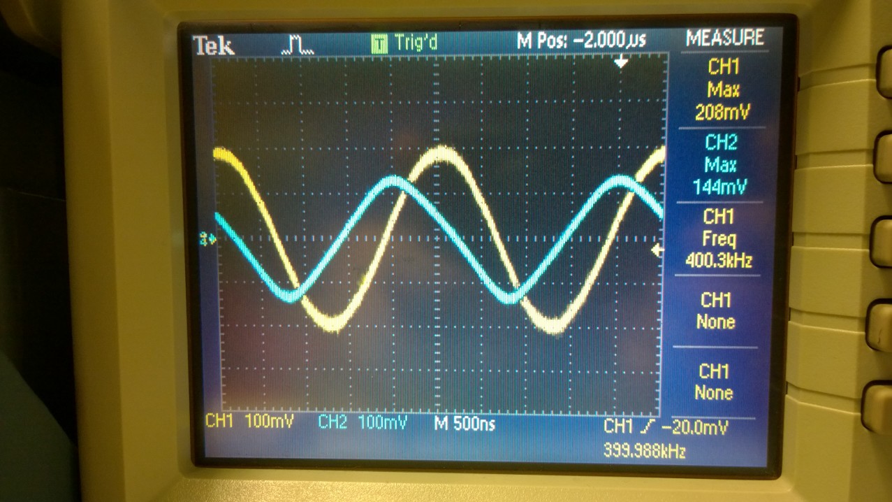
Non-inverting topology, gain of 1 V/V, 2.5 VCM
To calculate the bandwidth at the gain of 1, we must find the frequency at which
Vout = (1/sqrt(2))*Vin
for Vin = 200mV, this means Vout = 144mV and we find this output at a frequency of 400kHz.
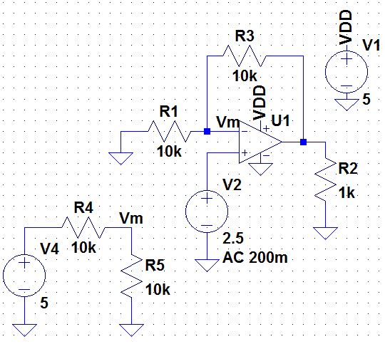
Frequency
generator at 400kHz, Vin = 100mV
Oscilloscope displaying Vin = 200mV, Vout =
144mV, frequency = 400kHz
| Gain | Vin | Vout | Frequency |
| 1 V/V | 200mV | 144mV | 400kHz |
NOTE: we always set our Vpp on our frequency generator to be half the actual Vpp so that we get acurate measurements.
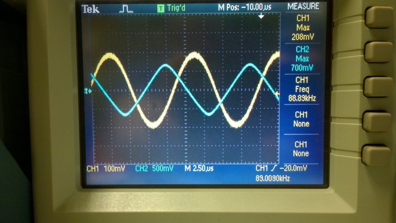
Gain 5:
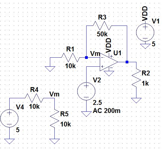
Non-inverting topology, gain of 5 V/V, 2.5 VCM
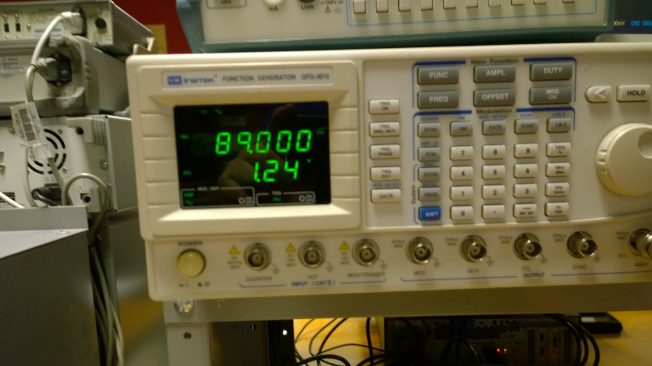
Frequency
generator at 89kHz, Vin = 1.24V
Oscilloscope displaying Vin = 200mV, Vout = 700mV, frequency = 89kHz
| Gain | Vin | Vout | Frequency |
| 5 V/V | 200mV | 700mV | 89kHz |
Gain 10:
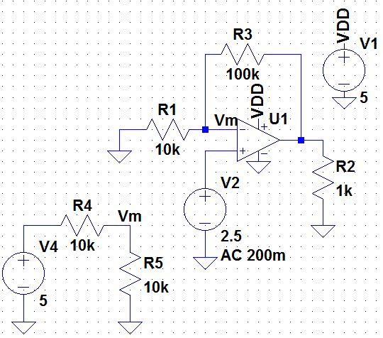
Non-inverting topology, gain of 10 V/V, 2.5 VCM
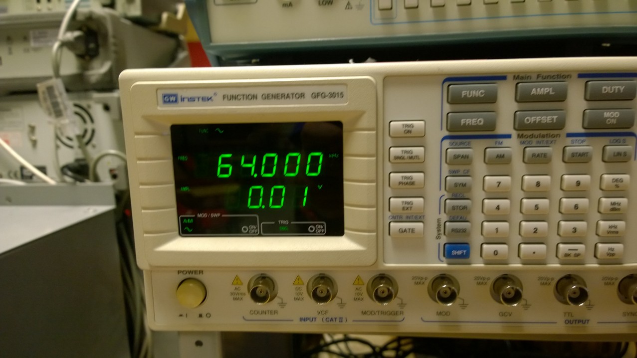
Frequency
generator at 64kHz, Vin = 10mV
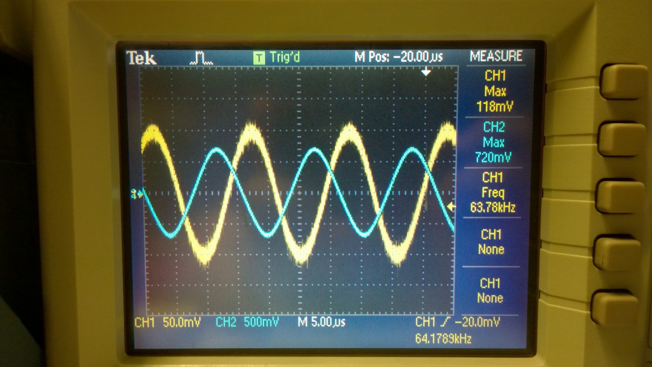
Oscilloscope displaying Vin = 118mV, Vout = 720mV, frequency = 64kHz
| Gain | Vin | Vout | Frequency |
| 10 V/V | 118mV | 720mV | 64kHz |
(Q) Repeat these steps using the inverting op-amp topology having gains of -1, -5, and -10.
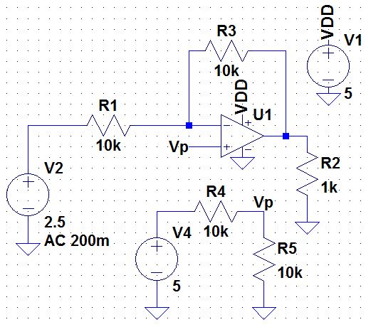

Inverting topology, gain of -1 V/V, 2.5 VCM Inverting topology, gain of -5 V/V, 2.5 VCM Inverting topology, gain of -10 V/V, 2.5 VCM
The results of the inverting topology are similar to the non-inverting topology, the only difference being a 180 degree phase shift. Thus we can collect the data onto a table for both topologies.
| Gain | Calculated Frequency | Measured Frequency | Accuracy |
| +/- 1 | 1.3MHz | 400kHz | 30% |
| +/- 5 | 260kHz | 89kHz | 34% |
| +/- 10 | 130kHz | 64kHz | 50% |
The reason our accuracy is so off is because the bandwidth calulations are bases of of a VDD = 30V and -VDD = 0. Thus, if we increased our VDD, we would see more accurate results.
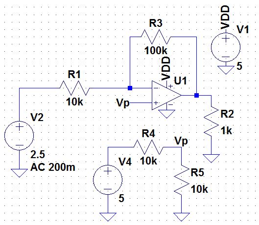
(Q) Design two circuits for measuring the slew-rate of the LM324. One circuit should use a pulse input while the other should use a sinewave input.
(A1) A simple way of measuring the slew rate, is to measure the time it takes from a output voltage to reach the input voltage of a 1 V/V gain. The input voltage will be the pulse and the output, the sinewave.
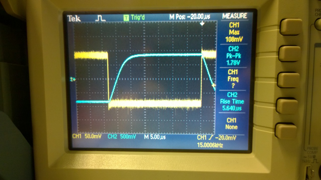
Slew rate of Pulse input with sinewave output.
Slew Rate = (1.78V/5.640us) = 0.3156V/uS
This is slightly different from the data sheet value wich is 0.4V/uS.
(A2) Of course, another easy way of calculating the slew rate is to do the same thing with a sinewave input and sinewave output.
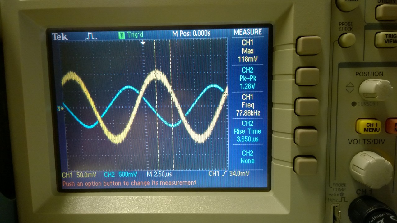
Sinewave input (yellow), sinewave output (blue)
Slew Rate = (1.28V/3.65us) = 0.3507V/uS
This is slightly different from the data sheet value wich is 0.4V/uS.
Conclusion
This lab highlighted the trade off between gain and bandwidth (higher gain = smaller bandwidth, higher bandwidth = smaller gain) and the limitations of the slew rate (speed) of an op-amp. We should be careful in our design in op-amp circuits, in that we operate them in their appropriate frequencies for their given gains and that our frequencies are not so fast that our op-amp can't match the output in time.