EE 420L - Lab 2
Operation of a compensated scope probe
() The schematic of a probe
() Waveforms of varying levels of compensation
() 1:1, 10:1, and 100:1 type of scopes
() Measurement of differrent capacitances
() Testing different components
------------------------------------------------------------
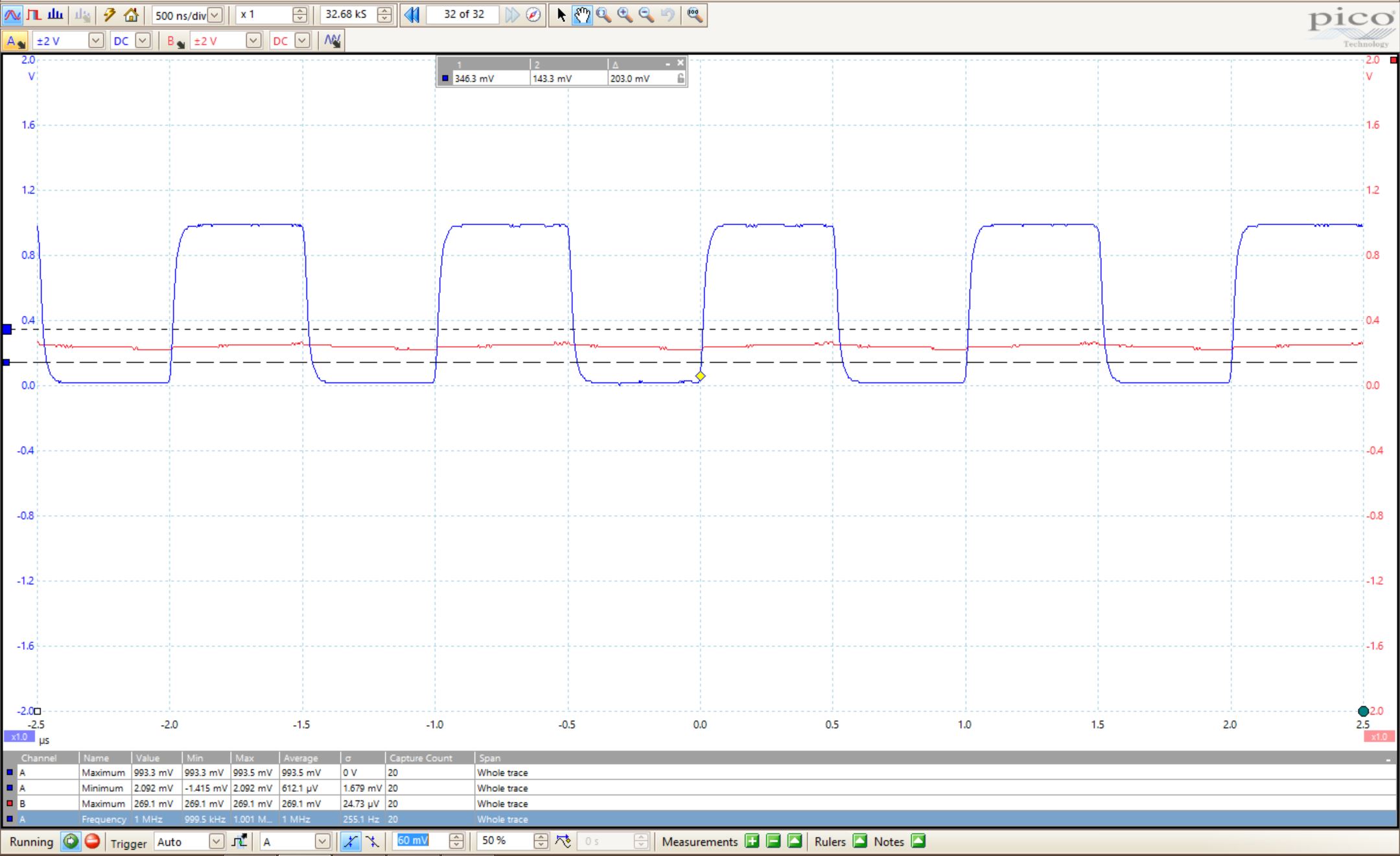
Waveforms
The
following waveforms come from the 'test probe' option on an
oscilloscope. The waveform will change dependng how 'compensated' the
scope tip is compared to the scope input.
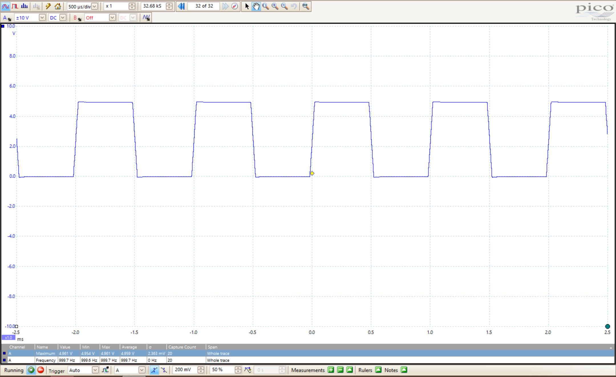
Compensated
The capacitance of the probe input matches the capacitance of the scope input in such as way that the impedences create a 10:1 ratio.
Over-compensated
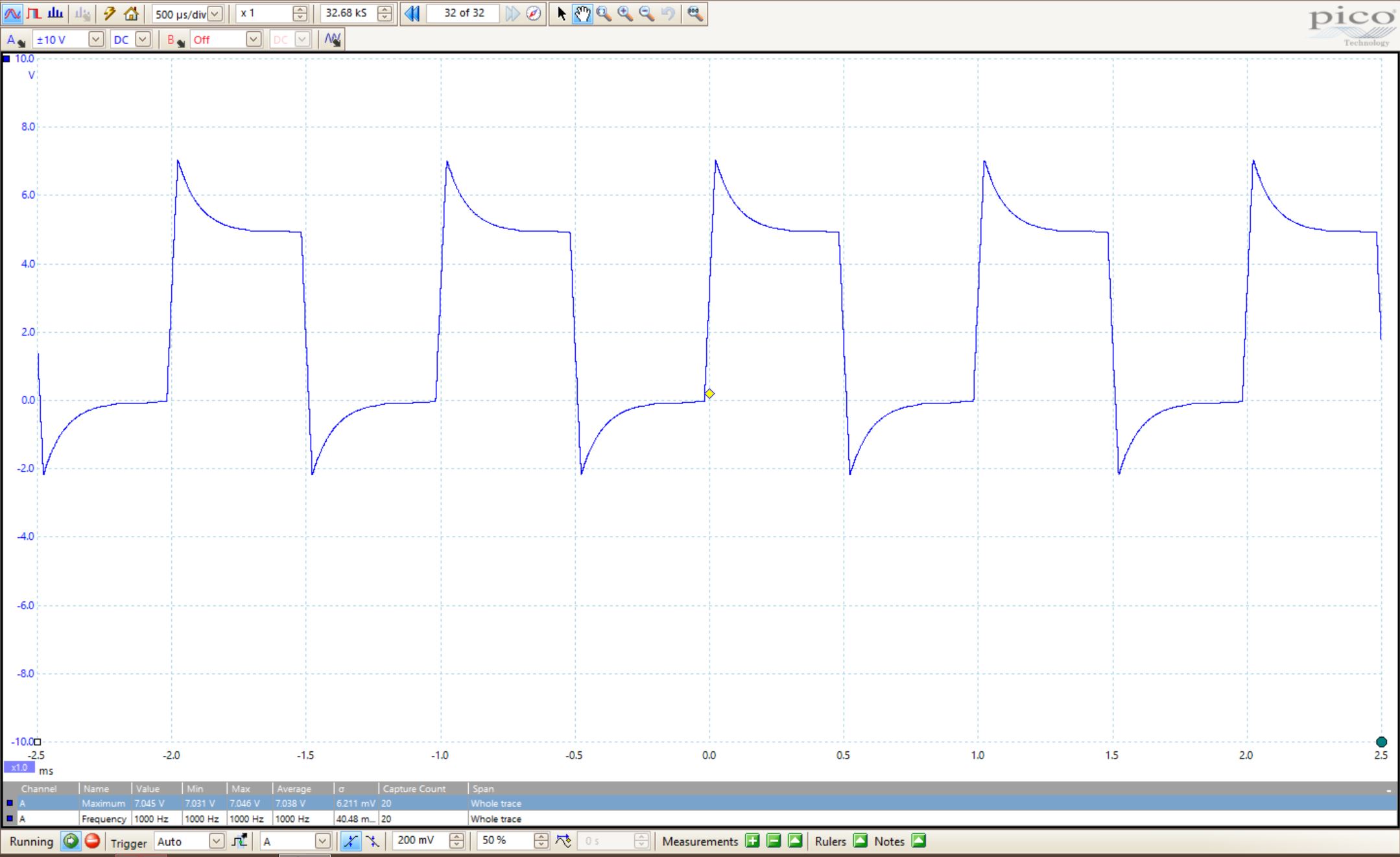
The ratio of impedances is skewed with probe input over capacitance.
Under-Compensated
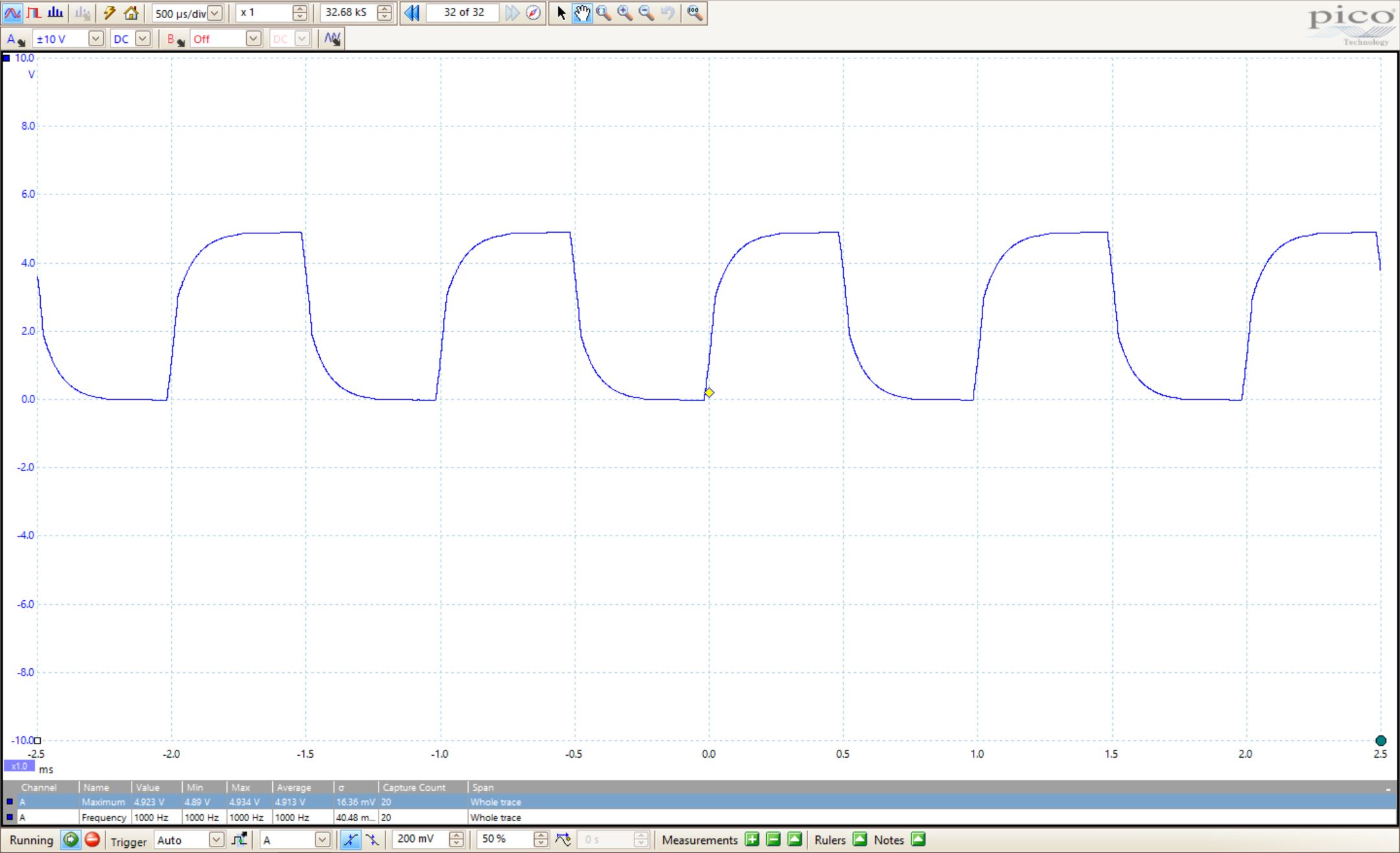
This time, the waveform is smoothed in that the probe input is under the required impedance to achieve the 10:1.
For our purposes, we will use a 10:1 probe, meaning that if we measure a node that is at 10v, we will measure 1v. This loss in gain is nessesary for speedy measurments and simulation programs can be made to ignre this mesurement and supplement the correct input.
Schematic
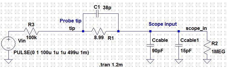
This schematic has the actual values of the probe that we measured from the probe.
Calculations
Simple derivation of the Vin/Vout relationship of the circuit, given a summation of impedances and suplimenting the values measured, gives us a gain of about 0.1 as to be expected.
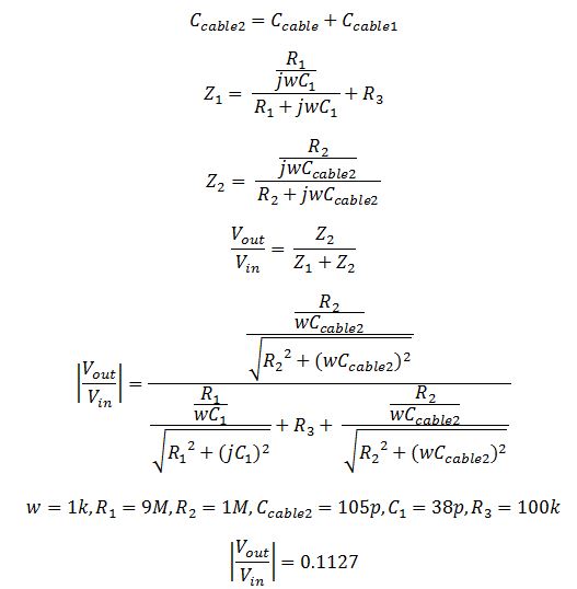
Capacitance of the Cable
One can measure the capacitance of the cable by using a scope, pulse generator, and a resistor. We use the relation of
Vout = Vinitial*e^(-t/RC)
We plut build a RC circuit and measure the Vout value at 1/e or 36% the time constant record that time. We also measure the RC time constant and Vin. From our experiment, we have:
0.3387=0.9868*e^((128.3*10^(-9))/(1k*C))
Solving for C gives us C = 124 pF. Measureing C with a multimeter, we find C = 104 pF. This result is 80% accurate.
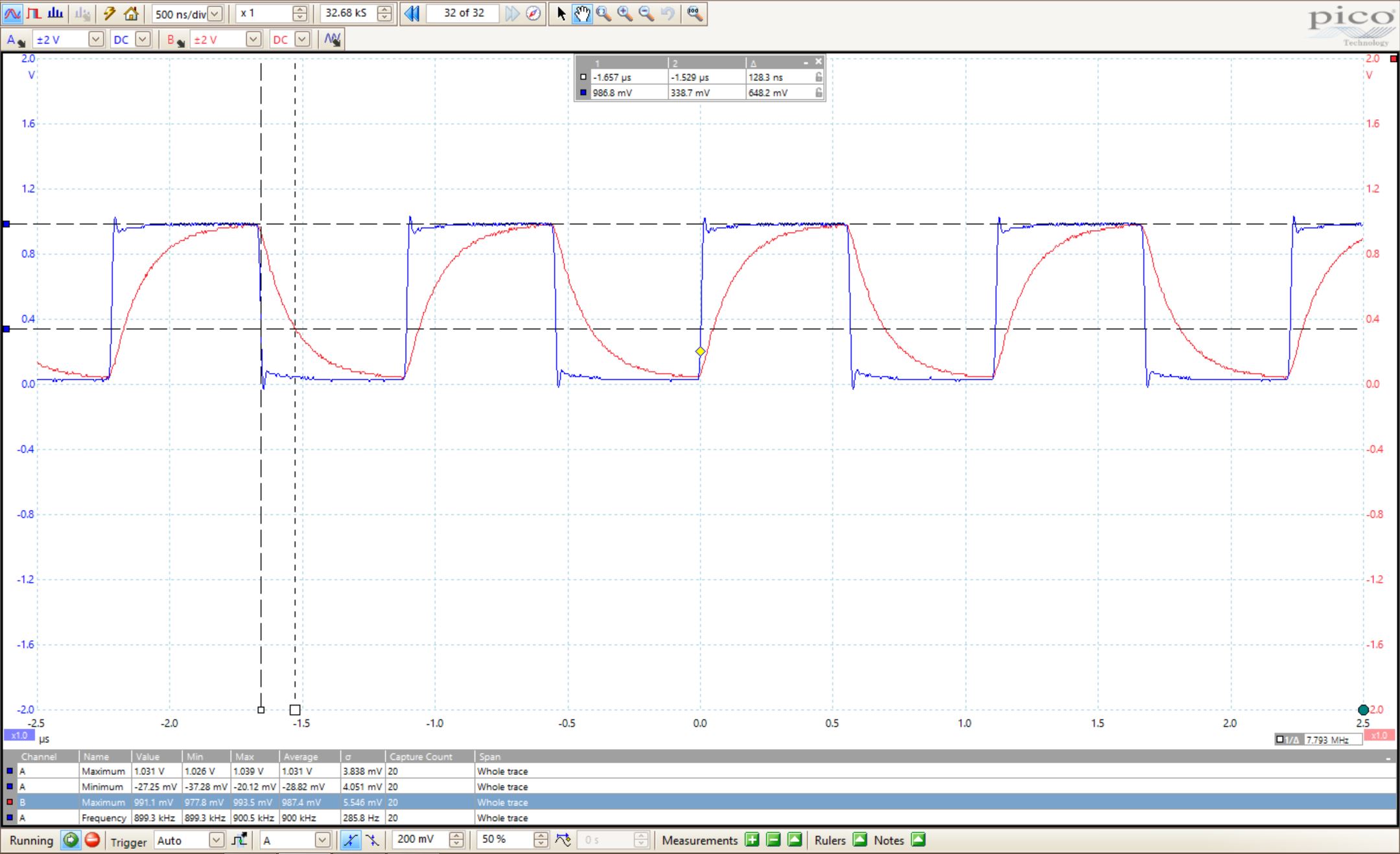
Differences in measurements in a voltage divider circuit
When measuring Vout from a voltage divider using two 100k resistors and applying a 0 to 1 V pulse at 1 MHz to the divider's input, we can measure the different waveforms that originate from varying compensation of the probe.
Compensation
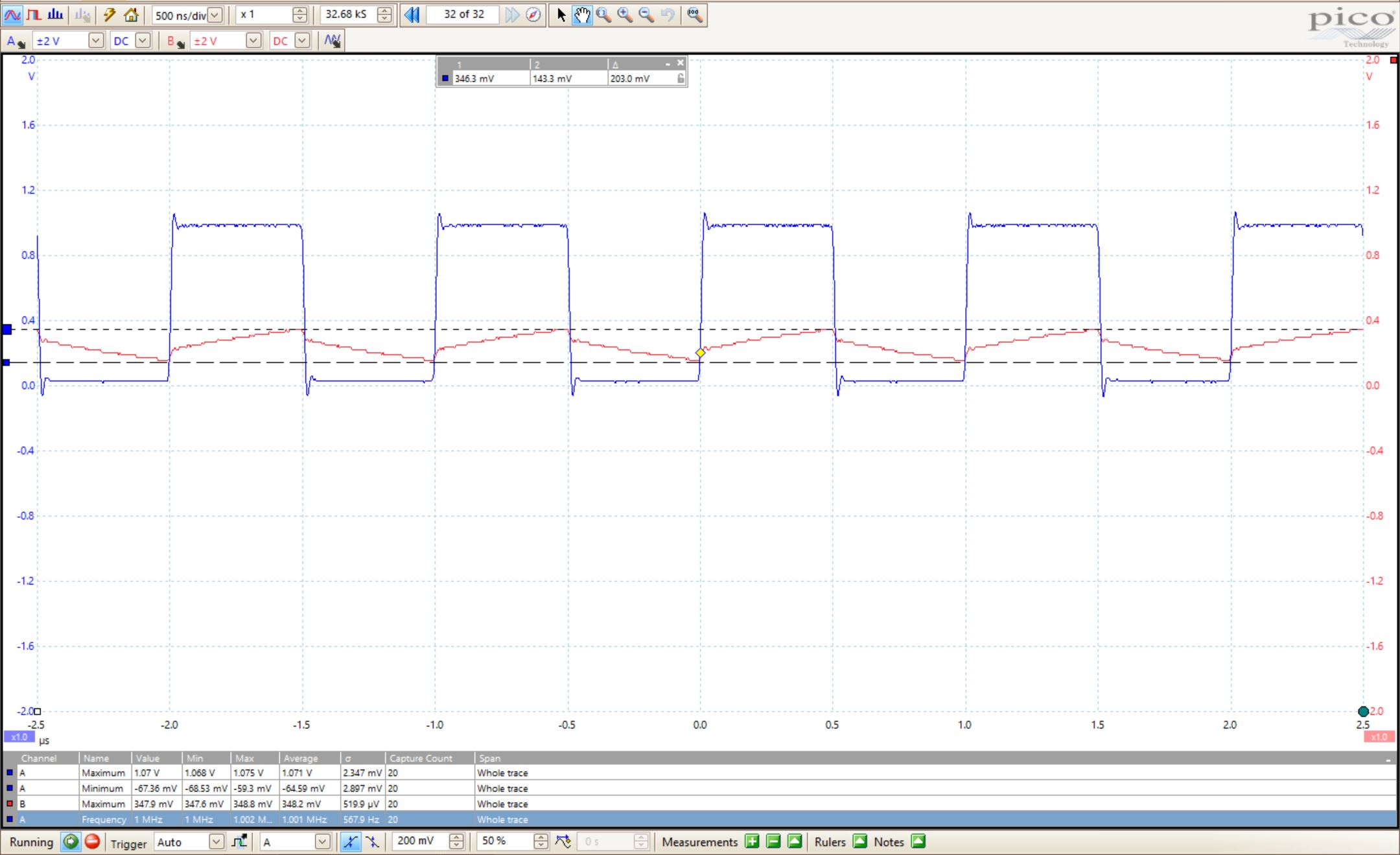
Sharp waveforms with defined peaks and valleys from the triangle output.
No Compensation
Too much gradation between peaks and valleys, waveform is no longer 'crisp' and is distored beyond recognition.
Test Point with no capacitance load
We can implement a test point on a printed circuit board so that a known length of cable could be connected directly to the board and not load the circuitry on the board by canceling the impedance with a matching impedance. For example, if our probe is loaded with capacitance from a capacitor, we can use impedance matching with an inductor to cancel out the overall impedance so only resitance remains.