Lab 7 - EE 420L Engineering Electronics II
For the following questions and experiments
assume VCC+ = +10 Volts
Experiment 1
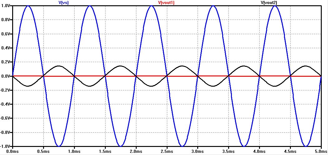
Below is a comparison between driving a speaker without (red, Vout1) and with (black, Vout2) an audio amplifier. The source resistance is 10k meaning that the source can supply 1 V (blue, Vs) at 100 uA maximum. The simulation files used to generate this figure are found in lab7_sims.zip.
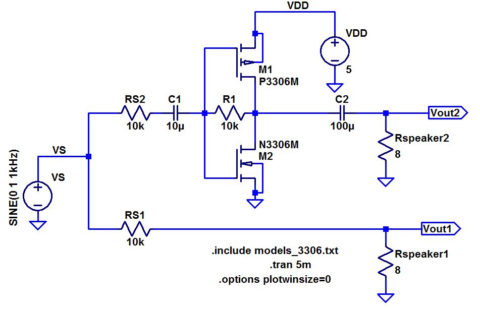
Our Audio Amplifier design consisted of the push pull amplifier seen in the previous lab and output stage
which was used to increase the gain in the circuit. At first, when just using the push pull amplifier, we observed
that
there was not enough gain as desired. Since we could not use any more
capacitors, we were limited in ideas
to enhance the gain without modifiying the push pull resistor. By feeding the output to a seperate NMOS transistor
we were able to use the source of the NMOS as our output. We added an 8
ohm resistor in parallel with the capcaitor
and
speaker such that the NMOS could operate at DC. Increasing the parallel
resistor (Rp) can slightly
increase
the gain. Any resistance value larger than 16 Ohms would not offer any
significant gains.
The
design we used is simulated below!


Next
we implemented the design on a breadboard. The amplifer output is shown
below when
we
only used the push pull amplifier without the output stage!

The amplifer output is shown below when we included the output stage!

The
power supply was able to show the current used by the
circuit which is handy in calculating the power usage.
Experimentally we using 0.32*10.7 = 3.4 Watts of energy.
Our simulation showed approximately 3.6Watts of energy being used. This variation can be
due
to the incorrect reading based off the power supply and or the
irregularities from the
experimental
MOSFETS used compared to the simulation values.
