Lab 3 - EE 420L
Engineering Electronics II
Author:
Matthew Meza
Email:
mezam11@unlv.nevada.edu
February
6, 2015
Op-Amps
I, Basic Topoligies, Finite Gain, and Offset
Click on any picture for its
full size!
Pre-lab work
Lab Description
- Learn how op-amps are used, their limitations, closed and
open-loop gian, offset voltage, common-mode voltage (VCM),
max input/output, input bias current, offset current.
Lab Data
For the following questions and experiments
assume VCC+ = +5V and VCC- = 0V.
- Knowing
the non-inverting input, Vp, is at the same potential as the inverting
input, Vm, (called the common-mode voltage, VCM)
what are the maximum
and minimum allowable common-mode voltages?

- The maximum allowable common-mode
voltage for our circuit is 3 [5-2] to 3.5 [5-1.5] volts.
- The minimum allowable common-mode voltage for our circuit is 0 volts.
- What is a good estimate for the op-amp's
open-loop gain?

- At 0Hz we
have around 110dB. AOL ~ 10^(110/20) = 316228 V/V
- The gain
decreases by approximatly 20dB/Decade
- What is a good estimate for the
offset voltage?

- A good estimate for
the offset is 7mV.
- For worst case design, we would
use the 9mV offset.
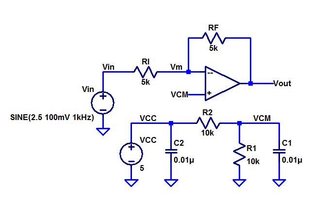
Build,
and test, the following circuit.
DC coupled
Offset Voltage
Input and Output
|
AC
Coupled
AC Input and Output
180 degrees out of phase
|
Clipping
when the input
voltage is too high
|

|

|

|
- What is the common-mode
voltage, VCM? Does VCM change? Why or why not?
- The common mode voltage is 2.5V DC.
The VCM does not change because is used as a reference for the
AC input signal to swing around. It is created by the 10k Voltage
divider at the positive input.
- What is the ideal
closed-loop gain?
- The
ideal closed-loop gain
is –Rf/Rin which is equal to 5k/5k = 1 or 0dB/Unity Gain.
- What
is the output swing
and what is it centered around?
- The output swing is approximately 200mV peak
to peak (+/-100mV peak). The output is centered around VCM which is
set at 2.5 V.
- What happens if the
input isn't centered around VCM, that is, 2.5 V?
- If
the input is not
centered around 2.5 V, then one may encounter various problems
such as clipping. A possible reason for an input to be
off from VCM is that the op-amp’s open-loop gain is not
sufficient to
pull Vm up to Vp. If the input voltage at the Vp terminal increases,
the output
voltages will decrease, and vice versa. Vp must be appropriately within
bound
of the positive supply rail.
- Provide a detailed
discussion illustrating that you understand what is going on.
- We
have a 5V input at VCC
which is voltage divided to 2.5 V at the positive input terminal, Vp.
This
voltage, then
appears at Vm, due to the very high open-loop gain
of the nearly non-ideal Op-Amp. This voltage is
then multiplied
by the closed-loop gain of the topology which is designated by
–Rf/Ri. In our case, this would be 1x (unity gain).
For AC, Vp is at AC ground. Consequently,
Vm is then at AC ground while the input AC voltage is multiplied by the
same
closed-loop gain. In conclusion, the output is centered around 2.5V
with an AC
swing of +/- 100mV (peak).
- What is the maximum
allowable input signal amplitude? Why?
- Since
our rails are set at
5V, and 0V. We could theoretically swing +/- 2.5 V. Anything larger,
will result
in
clipping of
the signal. The maximum allowable input signal would then be 2.5V.
Since real op-amps are non-ideal, the maximum allowable
input signal amplitude is less. In our case it may have an experimental
max swing of +/- 500mV (worst case when max VCM is 3 volts)
or a max swing of +/- 1V (most likely case when max VCM is 3.5 volts).
- What is the maximum
allowable input signal if the magnitude of the gain is increased to 10?
Why?
- By
increasing the magnitude
of the gain by 10, the largest input signal would be 250mV
theoretically because
the gain is ten times larger than before. (2.5/10).
- What
is the point of the 0.01 uF capacitors from VCC and VCM to ground?
- These capacitors are just to decouple the
voltages, and detract noise from the power supply.
- Are
these values
critical or could 0.1 uF, 1,000 pF, 1 uF, etc. capacitors be used?
- These
values could be
anything. They are used to hold the voltage at a node to a specific
value to
detract from sudden
swings. They are just charge buckets.
- The
data sheet shows that this op-amp has an input bias current that flows
out of the op-amp's inputs of typically 20 nA.
This current flows out
of both the non-inverting and inverting inputs through the resistors
connected to these inputs.
Show how the operation of
the circuit can be
effected if, for example, R1 and R2, are much larger. Explain what is
going on.
- If we had a
20nA input bias current
on each of the op-amp terminals, using a large resistor will produce a
larger
voltage at Vm, and
consequently,
Vp. This mismatch of voltages would then
change the output voltage of our op-amp.
- What is the offset
current? What does this term describe?
- The input
offset current is the difference between the input biase currents at VP
and VM.
It describes the mismatch between the two input currents of the op amp.
Explain
how the following circuit can be used to measure the op-amp's offset
voltage.
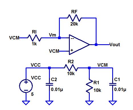
The circuit above
outputs 2.5
volts. Current flows from Vout to Vm through the 20k resistor while the
input bias current
flows from Vm. The input bias current is sometimes small compared to
the feedback current, although increasing the RF value
will lower the current that flows from Vout to Vm closer to Vm. This
will make the small ofset voltage more noticable as the
current through RF is around the same value as the input bias current.
- Measure the offset voltage of 4 different op-amps and compare
them.
Op-Amp
1 ~ +20mV
|
Op-Amp
2 ~ -20mV
|

|

|
Op-Amp
3 ~ 0mV
|
Op-Amp
4 ~ +40mV
|

|

|
Return
to EE 420 Labs