


Lab 2 - EE 420L
| Undercompensated | Overcompensated | Compensated Correctly |
| | |
| At the bottom right of the oscilloscope screen we can see two pins labeled "Probe Comp ~5V@1kHz" | Here is the probe we used, notice the black switch. It allows us to switch from x1 (1:1) to x10 (10:1). | The probe setting can be changed on the oscillosope to show the correct units. |
 |  |  |


| Square wave input vs squre wave output (resistor-cable circuit) | Measured capacitance of cable |
 |  |

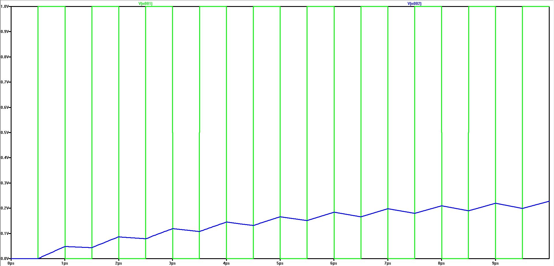
| Non-Compensated We see a flat line at approximately 0.3 volts. The large capacitance causes a large RC time constant. The frequency is so fast that the capacitance can not fully discharge | Compensated We see a charge and discharge signal around 0.3 volts. The smaller capacitance causes a smaller RC time constant. Although the frequency is fast, the small capacitance is able to dishcarge. |
 |  |
| Circuit | Analysis |
 |  |