Lab 7 - ECE 420L
Authored
by: Justin Le
Email: lej6@unlv.nevada.edu
April 10, 2015
Goal
Design
a simple audio amplifier for a frequency between 100 Hz and 20 kHz
using as many resistors and ZVN3306A/ZVP3306A MOSFETs as necessary,
with only one 10 uF and one 100 uF capacitor, powered by a 10 V supply
voltage. The audio signal originates from an MP3 player, and the
amplifier is connected to an 8-ohm speaker.
Pre-Lab
Review the operation of single-stage amplifiers that use the ZVN3306A and ZVP3306A MOSFETs.
Experiment
The design uses a push-pull amplifier (Figure 1a),
which has a gain of Rf*(gmn+gmp). By selecting Rf to be 10 kΩ, the gain
was set to be about 1000. In order to drive a speaker, however, the amplifier
must have an output impedance less than the speaker’s impedance. By the
principle of voltage division, if the speaker’s impedance is greater than the
amplifier’s output impedance, the voltage across the speaker is insufficient
for producing a sound from the speaker.
To reduce the output impedance, a source-follower was placed
at the output of the push-pull amplifier (Figure 1b). The
source-follower has a much smaller output impedance (Figure 3), which varies with
frequency between 3 Ω and 8 Ω (Figure 1d). This impedance allows for
a similar voltage to be dropped across the output stage and the speaker, which
has an impedance of 8 Ω.
Another
key trait of the source-follower is its unity
gain, which preserves the magnitude of the push-pull stage’s output.
The simulated
result is shown in Figure 1c. As seen in Figure 2a where the input is
on Channel 1, the output swing is comparable to the amplitude of the
input signal, indicating that an audible signal would be produced
by the speaker. Indeed, the sound of the audio signal was clearly
emanating from the speaker during the experiment.
Figure
1e shows that the input impedance does not vary greatly with frequency.
Its value, as calculated in Figure 3, is sufficiently large for
accepting an audio signal from an MP3 player.
The
power consumption of the circuit depends on the supply
voltage (10 V) and the circuit’s current draw (258 mA), which are shown
in Figure 2b. The calculation shown in Figure 3 indicates that the
design is not particularly power-efficient. Figure 3 also shows
calculations for the input impedance.
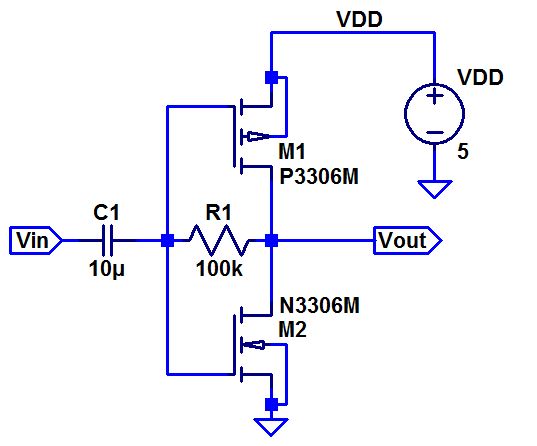
Figure 1a.
| 
Figure 1b.
|
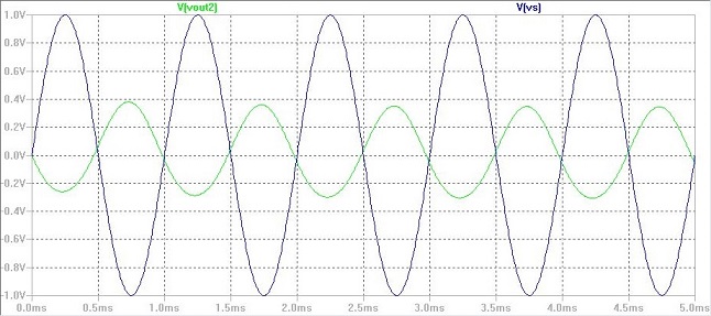
Figure 1c.
|

Figure 1d.
|
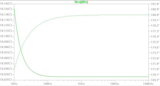
Figure 1e.
|
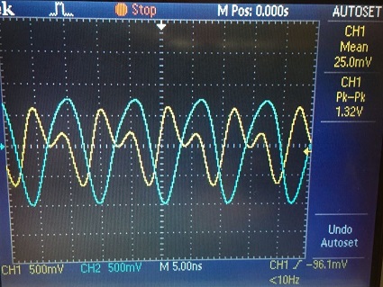
Figure 2a.
| 
Figure 2b.
|
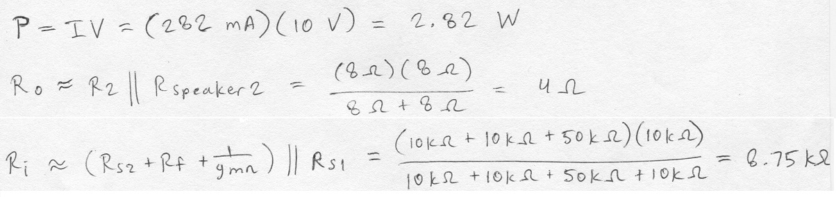
Figure 3.
|
Figures
1: Simulation.
2: Measurements.
3: Calculations.
Click to view all labs.