Lab 1 - ECE 420L
Authored
by: Justin Le
January 30, 2015
Pre-Lab
A personal account was established on cmosedu.com.
The tutorial on editing webpages was reviewed.
Experiment 1
An
RC circuit with a 1 kilo-ohm resistor and 1 uF capacitor was built and
provided with a sinusoidal input of 1 V peak at 200 Hz, as shown in
Figure 1a. As expected from the simulation in Figure 1d and calculation
in Figure 1e, the circuit outputs a sine wave with a peak of 0.7 V
(Figure 1b) across the capacitor and a time-shift of 680 us (Figure
1c), which approximates the calculated value of 715 us.
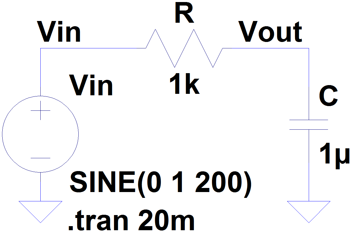
Figure 1a.
| 
Figure 1b.
|
Figure 1c.
|

Figure 1d.
| 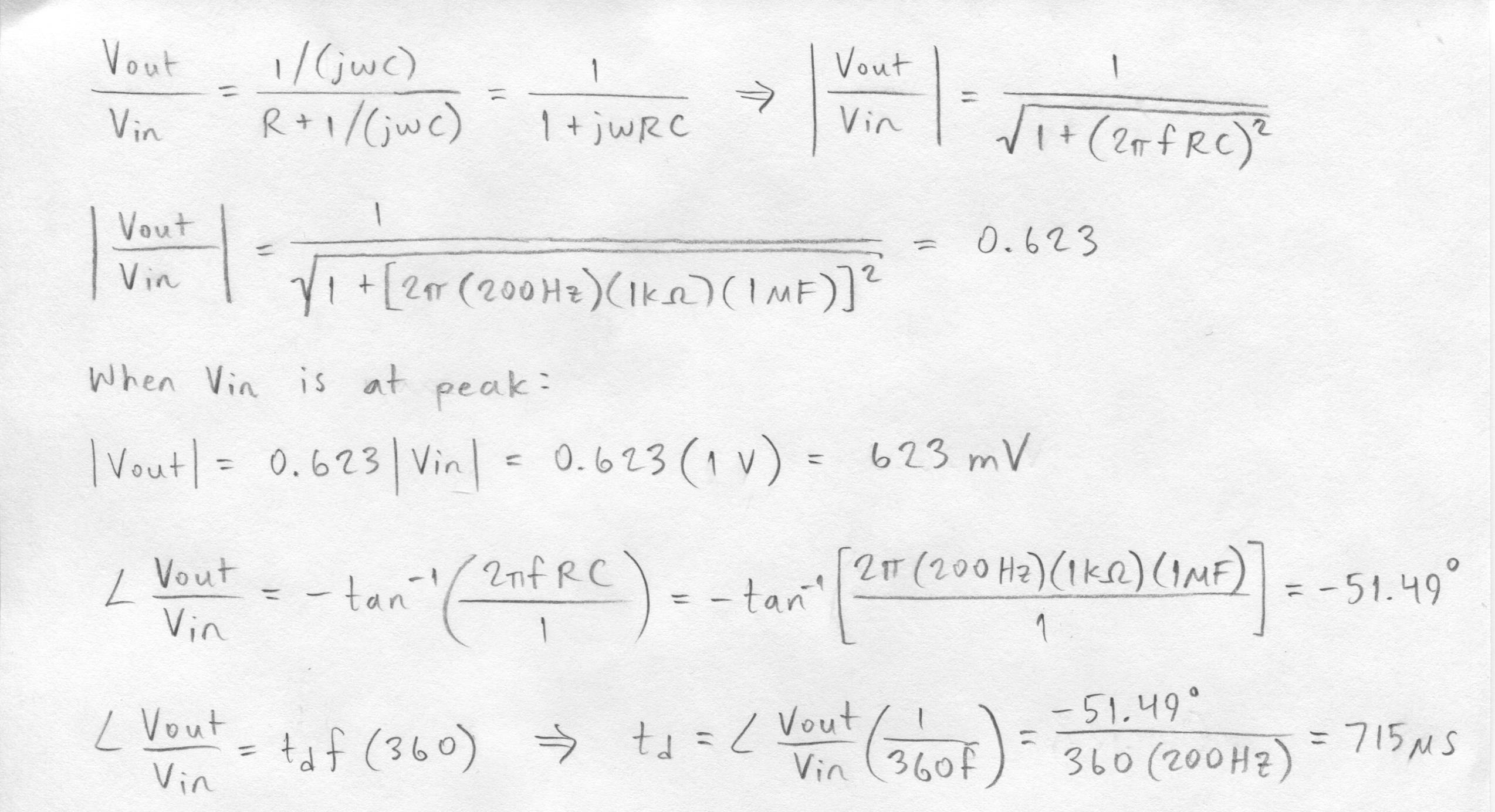
Figure 1e.
|
Experiment 2
The
circuit in Experiment 1 was modified to include a 2 uF capacitor in
parallel with the resistor. Again, the output was taken across the 1-uF
capacitor, showing a slightly higher peak of 760 mV (Figure 2b) and a
slightly greater time-shift of 120 us (Figure 2c), compared to the
calculated values of 694 mV and 95 us Figure 2e.
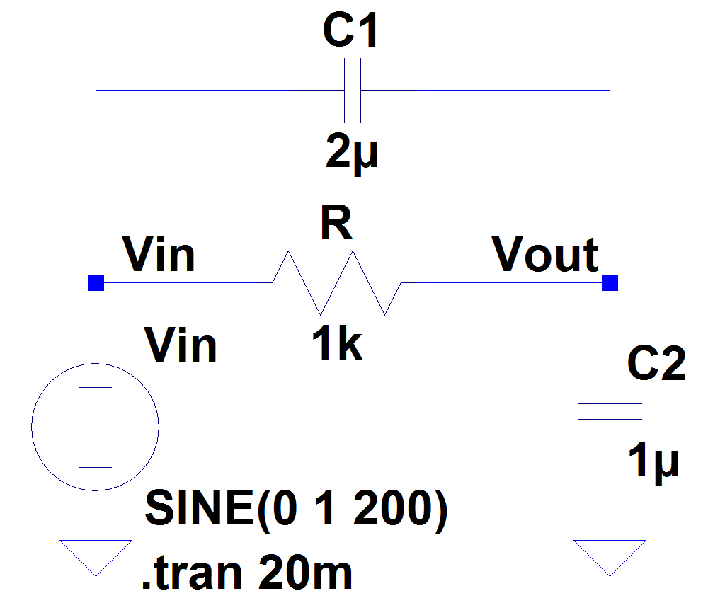
Figure 2a.
|
Figure 2b.
|
Figure 2c.
|

Figure 2d.
| 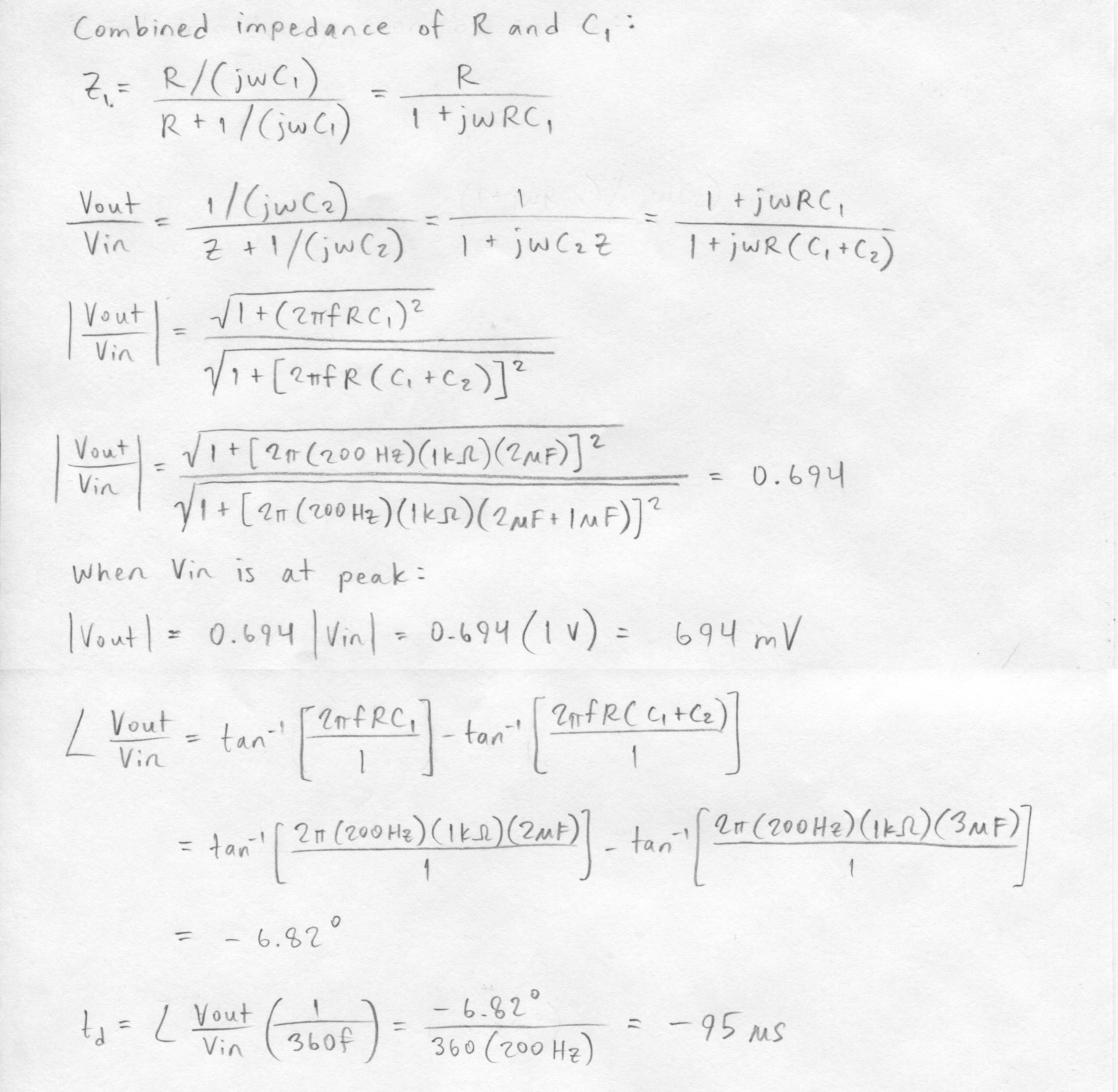
Figure 2e.
|
Experiment 3
Using
the same elements of the circuit in Experiment 1, another RC circuit
was built but with a pulse input of 0 to 1 V for a ~3 ms duration and
with a period of ~6 ns, as shown in Figure 3a. As expected
from the simulation in Figure 3d, the voltage across the capacitor
rises to a point just below the peak input during the pulse and falls
to its initial value in the time between pulses (Figure 1b).
Although the input period was 4 ns shorter in the experiment than in
the simulation, the output was not measurably affected.

Figure 3a.
|
Figure 3b.
|
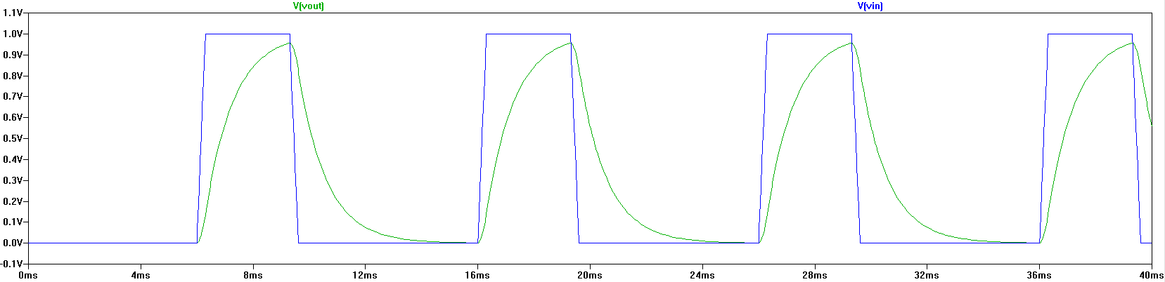
Figure 3c.
|
Figures
For Experiments 1 and 2:
a: Schematic.
bc: Laboratory results.
d: LTspice simulation.
e: Calculations.
For Experiment 3:
a: Schematic.
b: Laboratory result.
c: LTspice simulation.
Click to view all labs.