Lab 9 - ECE 420L
Authored
by Nicholas Banas,
Banasn1@unlv.nevada.edu
4/24/15
This lab uses the CD4007 to build a BMR controlled current mirror.
BMR construction
Using spice we constructed a BMR out of the CD4007 transistors.
The R value was calculatedd at 3.7k ohms while the minium VDD
calculated at 1.7V. Note: the width of M1 is twice the width of
M2.

The actual output of the BRM:

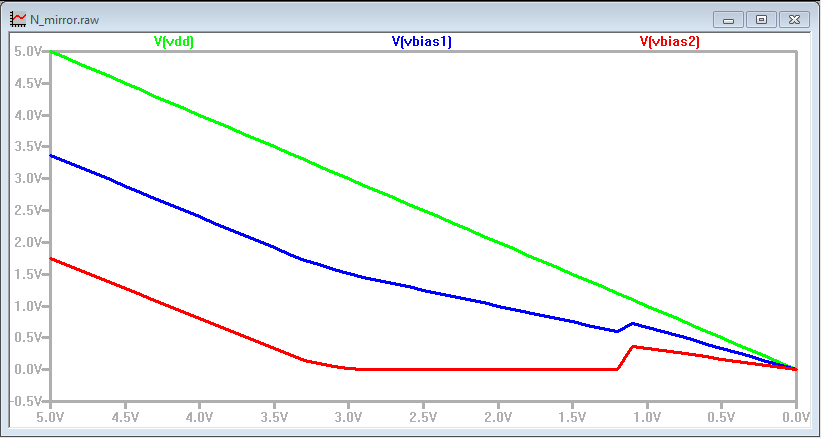
For all the lab measurements we swept Vdd from 5v to 0v over 9ms.
Note that the Pbias voltage track Vdd with a -1.7v offset while
the Nbias voltage remains constant at 1.4v until Vdd reaches ~1.7v.
The Nmos current mirror with Pmos Cascode output
The fist circuit uses an Nmos current mirror driven by our BMR to bias
a Pmos cascode output. The schematic is shown below.

The outputs measured were fairly stable and performed about as
expected. However the sim model required several adjustments to
parameters. The Nmos Vto required the largest adjustment from
1.7v to 1.1v.
After the model adjustmets, ths sim had close matching to the measured
results. There was a noticable error as Vdd hit 1V in the sims however.
The Pmos current mirror with Nmos Cascode output
The second circuit uses an Pmos current mirror driven by our BMR to
bias a Nmos cascode output. The schematic is shown below.

The
outputs measured were again fairly stable and performed about as
expected. The previous sim model adjustments worked well for this
circuit.
Again, there is a noticable error at Vdd clost to 1v for the sim.
This may be due to the model having M3 going back into saturation
as M2 goes into triode.
The SPICE Model Adjustments
The spice model was adjusted for this lab to make a better fit to the
measured results. After attempting several adjustments the VTO
and GAMMA adjustments to the NMOS model gave a fit that was acceptable.
| Spice Model for Lab 8 | Spice Model for Lab 9 |
 |  |