Bad Circuit
Design 2 - Biasing with a Voltage Source
A
simple way to ruin an otherwise good analog design is to bias with a voltage
source. Don’t do this
in
a simulation and, especially, don’t do this when you are testing a circuit!
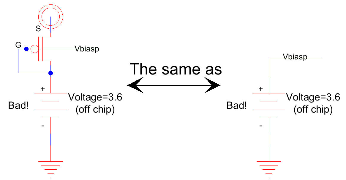
An
example bad design is seen below. A 3.6 V source is connected to a pad (say VDD
= 5 V) and used to
generate
Vbiasp. So why is this bad? Let’s assume the PMOS has
a bp of 400 uA/V2. We can then calculate
the
PMOS’s drain current, assuming a 900 mV threshold voltage, as (400uA/2)*(5 – 3.6 –
0.9)2 or 50 uA.
Now
let’s assume that there is noise on ground or VDD. This noise will appear
directly across the MOSFET’s S to G,
VSG , and change the drain current. So, if there is 100 mV (peak to peak) of noise on VDD or Vbiasp then the bias
current will vary from
40.5 uA to 60.5 uA (this is bad!)
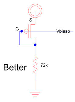
Next
consider using a resistor in place of the battery. The resistor’s value is
selected to set the bias current at 50 uA.
Again,
suppose we have a 100 mV of noise on ground or VDD. Now this noise is dropped
(mostly) across the resistor.
The
change in current becomes 100mV/72k or 1.4 uA (better than 20 uA.)
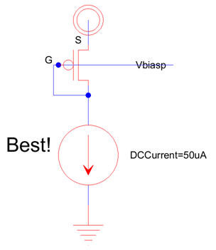
The
best way to generate Vbiasp is to use a current
source (current reference see the BMR in Figs. 20.15 and 20.22).
Power
supply or ground noise appears across the current source and thus neither VSG or the current in the
MOSFET
(or
any other MOSFETs connected to Vbiasp) vary.
Again,
don’t use voltage sources for biasing in simulations either. Use the bias
circuits seen in Figs. 20.43 and 20.47.
If
you need to adjust the bias point of your circuit change the resistor in the
BMR. Using voltage sources results in the biasing
not
changing with temperature, correctly with VDD, the way one bias source should
relative to another, or the way it
should
with process changes. This is important. A current source to a gate-drain
device (the last figure above) is an infinitely
better
way to provide biasing than using a voltage source.
Remember
this, the three most important things in
analog design are biasing, biasing, and biasing. Biasing sets the speed
(Eqs.
[9.36] and [9.55]), matching behavior (Eq. [20.8]), operating range (Eq.
[20.48] among many others), tolerance to power
supply
and ground noise, and static power dissipation in an analog circuit.
Notice
how, in the book, the biasing is detailed in every schematic. It’s not left to
the imagination of the reader because it’s
too
important!